
Combustible Ceiling Installation Instructions

Ceilin
Information is subject to change without notice or obligation. M-54738 Rev. C
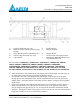
Notes: Dimensions denoted by ( ) are in millimeters.
Ceiling Radiation Damper
GBR-CRD
Combustible Ceiling Installation Instructions
𝑆𝑢𝑝𝑝𝑜𝑟𝑡 𝐿𝑒𝑛𝑔𝑡ℎ = 5
9
16
− 𝑅𝑒𝑠𝑖𝑙𝑖𝑒𝑛𝑡 𝐶ℎ𝑎𝑛𝑛𝑒𝑙 𝐻𝑒𝑖𝑔ℎ𝑡
4. The second supports are optional. An alternate installation using only first supports cut to the
truss/joist height.
5. The supports are to be flush mounted to the bottom of the joist/truss and secured using at
minimum 2” wood screws. Sizes for the fan supports are based on the presence of a resilient
channel, please refer to the appropriate UL floor/ceiling design. For reference:
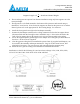
6. Install the fan support braces (H) on the fan/damper assembly.
7. Position the fan/damper assembly in the ceiling construction so that the fan support braces
(H) mount flush with the fan support 2x4’s installed in step 3. Drive in the 6D nails at the
ends of the fan support braces (H) into the 2x4’s to secure the assembly in the ceiling.
8. Secure the supplied plaster ground angles to the damper sleeve using the pre drilled holes in
the sleeve. No. 8 screws are supplied.
9. After the gypsum ceiling has been installed the picture frame (I), supplied with dampers, can
be secured to the assembly utilizing at minimum 2” long, No. 6 sheet metal screws, drill
pilot holes if necessary. Use one screw per side centered along the mounting strip.
10. Install the fan’s grille according to the standard fan installation documents.
Installation is valid for the following UL rated wood truss ceilings: L521, L546, L558, L562,
L574, L576, L581, L583, L585, P522, P533, P538, and P545