
Installation & Operating Manual

MODELS: GBR80 / GBR100
P
a
g
e 1.
INSTALLATION AND OPERATING INSTRUCTIONS
CEILING/WALL VENTILATION FAN
READ AND SAVE THESE INSTRUCTIONS
GENERAL SAFETY INFORMATION
1. Make sure that the electric service supply voltage is
AC 120V, 60Hz.
2. Follow all local electrical and safety codes, as well as
the Nation Electrical Code (NEC) and the
Occupation Safety and Healthy Act (OSH Act).
3. Always disconnect the power source before
working on or near the ventilating fan, motor or
junction box.
4. Protect the power cord from sharp edges, oil, grease,
hot surfaces, chemicals or other objects.
5. Do not kink the power cord.
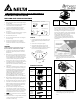
6. Do not install the unit where ducts are configured
as shown in Fig. A.
7. Provide suction parts with proper ventilation.
8. This unit is UL listed for use over a bathtub or
shower when installed in a GFCI protected branch
circuit.
WARNING
TO REDUCE THE RISK OF FIRE, ELECTRIC SHOCK, OR
INJURY TO PERSONS, OBSERVE THE FOLLOWING:
1. Use this unit only in the manner intended by the
manufacturer. If you have questions, contact the
manufacturer.
2. Before servicing or cleaning unit, switch power off
at service panel and lock the service disconnecting
means to prevent power from being switched on
accidentally. When the service disconnecting means
cannot be locked, securely fasten a prominent
warning device, such as a tag, to the service panel.
3. Installation work and electrical wiring must be done
by qualified person(s) in accordance with all
applicable codes and standards, including fire-rated
construction.
4. Sufficient air is needed for proper combustion and
exhausting of gases through the flue (chimney) of
fuel burning equipment to prevent back drafting.
Follow the heating equipment manufacturer’s
guideline and safety standards such as those
published by the National Fire Protection
Association (NFPA), and the American Society of
Heating, Refrigerating and Air-Conditioning
Engineers (ASHRAE), and the local code authorities.
5. When cutting or drilling into wall or ceiling, do not
damage electrical wiring and other hidden utilities.
6. Ducted fans must always be vented to the outdoors.
7. If this unit is to be installed over a tub or shower, it
must be marked as appropriate for the application
and be connected to a GFCI (Ground Fault Circuit
Interrupter) --- protected branch circuit.
8. Do not use this unit with any other solid-state
control devices. Solid-state control devices may
cause harmonic distortion, which can cause a motor
humming noise. (Avertissement: ne convient pas à
des régulateurs de vitesse à semi-conducteurs).
9. NEVER place a switch where it can be reached from
a tub or shower.
10. Not to be installed in a ceiling thermally insulated to
a value greater than R50. (This is required for
installation in Canada only).
Turning angle too large Duct shrink
Too many elbows Elbow near the body
Body
Fig. A
CAUTION
1. For General Ventilating Use Only. Do Not Use To
Exhaust Hazardous Or Explosive Materials And
Vapors.
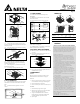
2. Not for use in cooking areas. (Fig. B)
3. This product must properly connect to the
grounding conductor of the supply circuit.
4. To reduce the risk of injury to persons, install the
fan at least 8.2 feet (2.5m) above the floor.
4
5
Cooking area
4
5
Do not install above or
inside this area
Cooking
Equipment
floor
SUPPLIED ACCESSORIES
Part name Appearance Quantity
Grille
1
Fan
1
Housing
1
Duct
Connector
(4’’)
1
Tapping
Screw
(Ø4×25)
8
Machine
Screw
(#8-32x5/16’’)
4
Hanger Bar
4
1. INSTALLATIONS
Proper insulation around the fan to minimize building
heat loss and gain. 4’’ circular duct is recommended for
installation. The ducting from this fan to the outside of
the building has a strong effect on the air flow, noise
and energy use of the fan. Use the shortest, straightest
duct routing possible for best performance, and avoid
installing the fan with smaller ducts than
recommended. Insulation around the ducts can
reduce energy loss and inhibit mold growth. Fans
installed with existing ducts may not achieve their
rated air flow.
MOUNT HOUSING WITH FLANGE(CELING/ WALL)
1-1. To bend the housing tabs out to 90 degree and
make housing tabs contact the bottom or front of
the joist.
Tabs
Joist
Tabs
Joist
1-2. The housing mounts with 4 screws (Ø4×25).
Screw housing to joist through lowest holes in
each mounting flange, then through the other
holes.
Fig. B