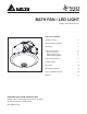
BATH FAN / LED LIGHT MODEL GBR100LED-DECOR TABLE OF CONTENTS READ AND SAVE THESE INSTRUCTIONS Address: 46101 Fremont Boulevard, Fremont, CA 94538 US Toll Free Number: 1-888-979-9889 www.deltabreez.
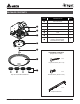
PACKAGE CONTENTS PART DESCRIPTION QTY ❶ Duct Connector 1 ❷ Fan Body 1 1 ❸ Grille Bracket 1 2 4 LED Module 1 5 Rod 1 6 Glass Shade 1 3 7 Decorative Caps and Finial nuts ( chrome, brushed nickel, brushed bronze, white) 4 5 HARDWARE CONTENTS (Images are to scale) 6 X8 Long Wood Screw ( ∅ 4 x 25) 7 X4 Cap set X 4 surface treatment Machine Screw ( #8-32 x 5/16”) X4 Suspension Bracket Model: GBR100LED-DECOR 2 4
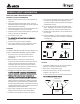
GENERAL SAFETY INFORMATION READ AND SAVE THESE INSTRUCTIONS GENERAL SAFETY INFORMATION 7. If this unit is to be installed over a tub or shower, it must be marked as appropriate for the application and be connected to a GFCI (Ground Fault Circuit lnterrupter) – protected branch circuit. 1. Make sure that the electric service supply voltage is AC 120V, 60Hz. 2. Follow all local electrical and safety codes, as well as the National Electrical Code (NEC) and the Occupational Safety and Health Act (OSH Act). 8.
PREPARATION Tools Required for Assembly (not included): Hammer, Flathead Screwdriver, Wire Nuts, Nails, Duct Tape, Phillips Head Screwdriver, Utility Knife Roof cap (with built-in damper) Short piece of flexible duct helps alignment and absorbs sound Helpful Tools (not included): Electric Drill, Drill Bits Fan housing WARNING: Turn off electricity at breaker box before beginning installation. or Carefully remove unit from carton.
ASSEMBLY INSTRUCTIONS BEFORE INSTALLATION Turn off power source. Review all safety precautions. 1 NEW CONSTRUCTION Tabs MOUNT HOUSING WITH FLANGE: Joist 1. To bend the housing tabs out to 90 degrees and make housing tabs contact the bottom of the joist. 2. The housing mounts with 4 long screws (ø 4×25). Screw housing to joist through lowest holes in each mounting flange, then through the other holes. 2 Joist Long Wood Screws USING SUSPENSION BRACKETS 3 3.
ASSEMBLY INSTRUCTIONS (Continued) b 1 EXISTING CONSTRUCTION–ACCESSIBLE FROM ABOVE a 1. Remove existing fan. Measure the ceiling opening to ensure it is large enough to accommodate the new a fan (8 in. x 8 1/4 in.) c 2 2. If this fan is not replacing an existing fan, be sure to cut a 8 in. x 8 1/4 in. opening for the fan body. .4"in. 8 1/94 n.4." 8 9i 3 3. Place housing in opening so that its bottom edge is flush with finished ceiling.
ASSEMBLY INSTRUCTIONS (Continued) 1 1. CONNECT WIRING A. Follow all local electrical code and ANSI/NFPA70. b B. NEVER place a switch where it can be reached from a tub or shower. C. Remove the fan junction box cover. Using wire nuts (not supplied) connect house wires to fan wires as shown in the wiring diagram on page 4. Wire connections are as follows: black and blue to live switch wire, white to neutral, green to ground. Reattach fan junction box cover. D. 14AWG (2.
CARE AND MAINTENANCE TURN OFF POWER SOURCE. REVIEW ALL SAFETY PRECAUTION. See safety information before proceeding. Routine maintenance should be done at least once a year. • Never use solvents, thinner or harsh chemicals when cleaning the fan. • Do not allow water to enter the motor. 1 • Do not immerse metal parts in water. • Do not immerse resin parts in water over 140º F. 1. carefully unscrew cap, finial nut and rod to remove glass shade and LED module. 2 2.
TROUBLESHOOTING PROBLEM The fan is not turning on The fan seems louder than it should POSSIBLE CAUSE CORRECTIVE ACTION 1. Power off 1. Make sure power supply is on. 2. Faulty switch 2. Test or replace switch. 3. Faulty wire connection 3. Check wire in switch box. 1. CFM too great 1. Be sure the CFM rating on the fan matches the size of your room. 2. Damper not working properly or damaged 2. Check damper to ensure it is opening and closing properly.
DIMENSIONS 8“ 8 1/4 “ 4“ 5 3/4 “ 4 5/8 “ 14 “ PRODUCT SPECIFICATIONS SPECIFICATIONS Model No. Voltage (V) Frequency (Hz) Fan Power @0.1”SP (W) Air Flow @0.1”SP (CFM) Noise @0.1”SP (Sones) Weight (lb.) LED light spec. GBR100LED-DECOR 120 60 13.0 100 1.5 9.6 13 Watts, 950Lumens, 3000K LIST OF COMPATIBLE DIMMERS(NOT SUPPLIED) NO. Brand Model NO.
WARRANTY DELTA ELECTRONICS THREE YEAR LIMITED WARRANTY Delta Electronics Inc. (“Delta Electronics”) warrants to the original consumer purchaser in the USA that the Breez ventilation fan products will be free from defects in material or workmanship. This warranty is limited to three (3) years from the original date of purchase. Limitations and Exclusions 1. During the warranty period, a replacement for any defective product will be supplied free of charge for installation by the consumer.
Model: GBR100LED-DECOR 12