
Non-Combustible Ceiling Installation Instructions

Ceilin
Information is subject to change without notice or obligation. M-54740 Rev. D
Notes: Dimensions donated by ( ) are in millimeters.
Ceiling Radiation Damper
ITG-CRD
Non-Combustible Ceiling Installation Instructions
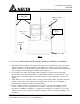
Fig. 1
For fan models: ITG80, ITG50, ITG100, ITG80H, ITG80LED, ITG70LED and ITG50LED.
1. Install the radiation damper onto the inlet side of the fan so that the holes in the sleeve align
with mounting holes on the fan using the four #10-32 x ¼” long screws provided with the
damper assembly (general installation). The mounting holes of the fan should be aligned with
the mounting holes of the damper assembly (refer to Figure 1).
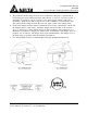
2. For a damper used with a fan equipped with a grill light, route the wire from the grille
through the notch on the damper frame. Use the supplied bracket to secure the wire to the
damper frame. Attach the bracket to the frame using one of the supplied #8-18 screw (see
Figure 3)
3. If the damper is to be used with a fan not equipped with a lighted grille, attach the same wire
bracket (rotated 180°) to the frame using the supplied #8-18 screw as seen in Figure 2.
Ensure that the bracket covers the notch in the frame.
4. Once the damper assembly is secured to the fan, turn it over so that the damper is at the
bottom. The fan can now be installed by two methods. The first is by utilizing vertical
hangar wires, minimum 12 SWG (2.7), attached to the damper sleeve (require one per side).
The second is to use the suspension bracket assembly provided by the fan manufacture (sold
separately).
Damper and Fan
Assembly
Fire Rated
Ceiling
Steel Hanger Wire
(12 SWG Min)
Fan Grille
10-32 x ¼” L
Screw
10-32 x ¼” L
Screw