
Installation & Operating Manual

MODEL: ITG50LED / ITG80LED
INSTALLATION AND OPERATING INSTRUCTIONS
CEILING VENTILATION FAN
READ AND SAVE THESE INSTRUCTIONS
General Safety Information
1. Make sure that the electric service supply
voltage is AC 120V, 60Hz.
2. Follow all local electrical and safety codes, as
well as the National Electrical Code (NEC) and
the Occupational Safety and Healthy Act
(OSHAct).
3. Always disconnect the power source before
working on or near the ventilating fan, motor or
junction box.
4. Protect the power cord from sharp edges, oil,
grease, hot surfaces, chemicals or other
objects.
5. Do not kink the power cord.
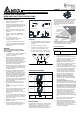
6. Do not install the unit where ducts are
configured as shown in Fig. A.
7. Provide suction parts with proper ventilation.
8. This unit is UL listed for use over a bathtub or
shower when installed in a GFCI protected
branch circuit.
WARNING
TO REDUCE THE RISK OF FIRE, ELECTRIC
SHOCK, OR INJURY TO PERSONS, OBSERVE
THE FOLLOWING:
1. Use this unit only in the manner intended by the
manufacturer. If you have any questions,
contact the manufacturer.
2. Before servicing or cleaning the unit, switch
power off at service panel and lock the service
disconnecting means to prevent power from
being switched on accidentally. When the
service disconnecting means cannot be locked,
securely fasten a prominent warning device,
such as a tag, to the service panel.
3. Installation work and electrical wiring must be
done by qualified person(s) in accordance with
all applicable codes and standards, including
fire-rated construction.
4. Sufficient air is needed for proper combustion
and exhausting of gases through the flue
(chimney) of fuel burning equipment to prevent
back drafting. Follow the heating equipment
manufacturer’s guideline and safety standards
such as those published by the National Fire
Protection Association (NFPA), and the
American Society for Heating, Refrigeration and
Air Conditioning Engineers (ASHRAE), and the
local code authorities.
5. When cutting or drilling into ceiling, do not
damage electrical wiring and other hidden
utilities.
6. Ducted fans must always be vented to the
outdoors.
7. If this unit is to be installed over a tub or shower,
it must be marked as appropriate for the
application and be connected to a GFCI
(Ground Fault Circuit Interrupter) – protected
branch circuit.
8. Do not use this unit with any other solid-state
control device. Solid-state controls devices may
cause harmonic distortion, which can cause a
motor humming noise.
9. NEVER place a switch where it can be reached
from a tub or shower.
10. Not to be installed in a ceiling thermally
insulated to a value greater than R40. (This is
required for installation in Canada only).
Turning angle too large Duct shrink
Too many elbows Elbow near the body
Body
Minimum 18 in.
CAUTION
1. For General Ventilating Use Only. Do Not Use
To Exhaust Hazardous Or Explosive Materials
And Vapors.
2. Not for use in cooking area. (Fig. B)
3. This product must properly connect to the
grounding conductor of the supply circuit.
4. To reduce the risk of injury to persons, install
the fan at least 8.2 feet (2.5m) above the floor.
Cooking area
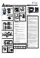
SUPPLIED ACCESSORIES
Part name
Appearance Quantity
Grille
1
Fan
1
Housing
1
4” Duct
1
Screw
(M4x12)
3
INSTALLATIONS
Proper insulation around the fan to minimize building
heat loss and gain. 4” circular duct is recommended
for installation. The ducting from this fan to the
outside of building has a strong effect on the air flow,
noise and energy use of the fan. Use the shortest,
straightest duct routing possible for best performance,
and avoid installing the fan with smaller ducts than
recommended. Insulation around the ducts can
reduce energy loss and inhibit mold growth. Fans
installed with existing ducts may not achieve their
rated air flow.
External timer/dimmer switch can be used. Please
contact Delta Breez customer service and consult
with a licensed electrician for compatibility.
Install with wood frame
Model No. ITG50LED / ITG80LED
Install Dim.
(Inch)
7-1/2 x 7-1/4
1. Remove motor plate from housing by
removing three screws. (Fig. C)
2. Remove wiring cover from housing by pulling
straight out. Choose a hole and use a slotted
screwdriver to remove it. (Fig. D)
3. Follow all local electrical and safety codes.
NEVER place a switch where it can be
reached from a tub or shower. Connect wires
as shown in wiring diagrams. (Fig. E)
4. Using wire nuts(not provided), connect house
power cable to ventilating fan wires. 14 AWG
(2.1 mm
2
) is the smallest conductor that shall
be used for branch-circuit wiring. (Fig. F)
5. Insert the duct into the duct connector and
tape all ductworks connection to make them
secure and airtight. Install the duct with a
gradient 1°~2° to the outside. (Fig. G)
6. New installation prior to finishing the
ceiling: Insert the fan between joists. Make
sure the fan body is level and perpendicular
with the joist. (Fig. H)
7. Replacement installation: After making
electrical and ductwork connections (see steps
2~5), nail housing in place. Drive nails through
the housing where indicated by arrows. (Fig. I)
8. New installation in an existing ceiling: Bend
tabs outward 90°(Use a screw driver if desired)
and position housing so that tabs rest against
bottom edge of joists (or front of stud). Nail
housing to joist or stud using four nails to
ensure a solid, quiet installation. Ceiling
installations: Tabs on opposite side of housing
can be bent outward to rest on top of 1/2"
ceiling material and provide extra stability. (Fig.
J)
9. Plug in the motor and locking the fan body
back by using three screws. (Fig. C)
10. Squeeze grille springs together and insert
springs into slots in motor plate. Push grille up
against ceiling. When the power on, check for
abnormal vibration or sound. Insert the
mounting springs into the slots and mount the
grille to the body. (Fig. K)
Fig. A
Fig. B