VENTILATION FAN / LED LIGHT / LED NIGHT LIGHT MODEL REC80LED TABLE OF CONTENTS READ AND SAVE THESE INSTRUCTIONS Address: 46101 Fremont Boulevard, Fremont, CA 94538 US Toll Free Number: 1-888-979-9889 www.deltabreez.
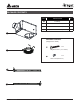
PACKAGE CONTENTS PART DESCRIPTION QTY ❶ Fan Body 1 ❷ LED Module 1 ❸ Suspension bracket Ⅰ 13”(318.5mm) 2 ❹ Suspension bracket Ⅱ 13”(318.
GENERAL SAFETY INFORMATION READ AND SAVE THESE INSTRUCTIONS GENERAL SAFETY INFORMATION 7. If this unit is to be installed over a tub or shower, it must be marked as appropriate for the application and be connected to a GFCI (Ground Fault Circuit lnterrupter) – protected branch circuit. 1. Make sure that the electric service supply voltage is AC 120V, 60Hz. 8. Do not use this unit with any other solid-state control device.
PREPARATION Tools Required for Assembly (not included): Hammer, Flathead Screwdriver, Wire Nuts, Nails, Duct Tape, Phillips Head Screwdriver, Utility Knife Short piece of flexible duct helps alignment and absorbs sound Helpful Tools (not included): Electric Drill, Drill Bits WARNING: Turn off electricity at breaker box before beginning installation. Fan housing or Carefully remove unit from carton.
WIRING DIAGRAM Triple Switch Control - With three switches, all three features can be controlled independently.
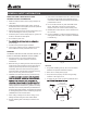
ASSEMBLY INSTRUCTIONS 1 1. For joist spacing 16 in. - 24in., insert suspension bracket I ❷ and suspension bracket II ❸ into the bracket cover on the duct connector side and the back of the fan body ❶ . Suspension 2 Bracket I 1 Fan Body Hardware A B X8 3 Suspension X4 Bracket II 16"(406mm) 19.2"(487mm) 24"(609mm) 2 2. Make sure there will be a gap (>1/8 inches (3.2mm)) between bottom of fan body and ceiling. Suspension Bracket Joist >1/8" (3.
ASSEMBLY INSTRUCTIONS 3 3. Install the suspension brackets to the joists with long wood screws, and secure the suspension brackets to the fan body ❶ by using the short screws (provided). Joist Joist 1 Fan Body a 4 Wire nut 4. Remove the fan junction box cover . Using wire nuts (not supplied), connect house wires to fan wires as shown in the wiring diagram on page 4. Reattach fan junction box cover . b a Junction Box cover 5 (not supplied) 5. Connect a 4 in. circular duct and vent to the outside.
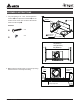
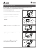
ASSEMBLY INSTRUCTIONS 7 7. Insert the LED light connector into the fan body. 2-Slots LED light connector 2-Springs LED module 8 8. Attach LED module ❷ by pinching mounting springs a and insert into the narrow rectangular slots in fan body.
CARE AND MAINTENANCE See safety information before proceeding. Routine maintenance should be done at least once a year. • Never use solvents, thinner or harsh chemicals when cleaning the fan. • Do not allow water to enter the motor. 1 • Do not immerse metal parts in water. • Do not immerse resin parts in water over 140º Fahrenheit. Turn off power source. Review all safety precautions. 2 1. To remove LED module ❷ , squeeze springs and pull down. 2 2.
TROUBLESHOOTING PROBLEM The fan is not turning on The fan seems louder than it should POSSIBLE CAUSE CORRECTIVE ACTION 1. Power off 1. Make sure power supply is on. 2. Faulty switch 2. Test or replace switch. 3. Faulty wire connection 3. Check wire in switch box. 1. CFM too great 1. Be sure the CFM rating on the fan matches the size of your room. 2. Damper not working properly or damaged 2. Check damper to ensure it is opening and closing properly.
8 1/4 (209.6) 3 7/8 (97.2)Dia. DIMENSIONS 6 1/2 (161.6)Dia. 7 1/2 (190.0) 8 7/8 (226.2) 1/2 (12.0) Unit: Inches(mm) 4 (100.0) 12 3/4 (324.
WARRANTY DELTA ELECTRONICS THREE YEAR LIMITED WARRANTY Delta Electronics Inc. (“Delta Electronics”) warrants to the original consumer purchaser in the USA that the Breez ventilation fan products will be free from defects in material or workmanship. This warranty is limited to three (3) years from the original date of purchase. Limitations and Exclusions 1. During the warranty period, a replacement for any defective product will be supplied free of charge for installation by the consumer.