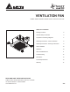
VENTILATION FAN MODEL SIG80 / SIG80M / SIG80D / SIG110 / SIG110H / SIG110D TABLE OF CONTENTS Package Contents 2 General Safety Information 3 Preparation and Wiring Diagrams 4 Assembly Instructions - New Construction 5 Assembly Instructions - Existing Construction 6 Grille Installation 10 Operation 10 Care and Maintenance 11 Troubleshooting 12 Dimensions 13 Product Specifications 13 Warranty 14 READ AND SAVE THESE INSTRUCTIONS Address: 46101 Fremont Boulevard, Fremont, CA
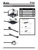
PACKAGE CONTENTS 1 2 PART DESCRIPTION QTY ❶ Fan Body 1 ❷ Grille 1 ❸ Suspension bracket Ⅰ 13”(318.5mm) 2 ❹ Suspension bracket Ⅱ 13”(318.
GENERAL SAFETY INFORMATION READ AND SAVE THESE INSTRUCTIONS GENERAL SAFETY INFORMATION 7. If this unit is to be installed over a tub or shower, it must be marked as appropriate for the application and be connected to a GFCI (Ground Fault Circuit lnterrupter) – protected branch circuit. 1. Make sure that the electric service supply voltage is AC 120V, 60Hz. 8. Do not use this unit with any other solid-state control device.
PREPARATION Tools Required for Assembly (not included): Hammer, Flathead Screwdriver, Wire Nuts, Nails, Duct Tape, Phillips Head Screwdriver, Utility Knife Helpful Tools (not included): Electric Drill, Drill Bits Roof cap (with built-in damper) Short piece of flexible duct helps alignment and absorbs sound Fan housing or WARNING: Turn off electricity at breaker box before beginning installation. Carefully remove unit from carton.
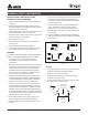
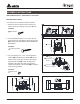
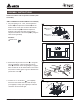
ASSEMBLY INSTRUCTIONS NEW CONSTRUCTION – ATTACHING TO THE JOIST BEFORE INSTALLATION Turn off power source. Review all safety precautions. 1. Attach the duct connector from the housing can inside, and secure using the duct screw (M4x12). 1 Insert tab into slot in housing Duct screw(M4X12) from Parts Bag Hardware C Duct Screw 2. If spacing between joists is 12 in. apart, use four long wood screws (provided) to attach the fan body ❶ to ceiling joists, NO NEED FOR SUSPENSION BRACKETS.
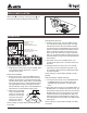
ASSEMBLY INSTRUCTIONS 4 4. Remove the fan junction box cover a . Using wire nuts (not supplied), connect house wires to fan wires b as shown in the wiring diagram on page 4. Wire connections are as follows: black to live switch wire, white to neutral, green to ground. Reattach fan junction box cover c . b c a 5 5. Connect a 4 in. circular duct a (not supplied) and vent to the outside. Secure it with duct tape (not supplied) or clamp (not supplied) to make the connection secure and air tight.
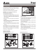
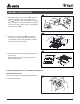
ASSEMBLY INSTRUCTIONS 2. Measure the opening to ensure it is large enough to accommodate the new fan body (10.25 in. x 10.25 in.). 2 3. If this fan is not replacing an old fan, be sure to cut a 10.25 in. x 10.25 in. opening for the fan body ❶ . 3 Install from below, no need for suspension brackets (no attic access) 4 .4"in. 5 10.29 n. .4i" .295 10 a A 4. Remove fan unit by removing 3 screws. 3.5 in . 6 5. A piece of wood (not supplied) is screwed in from below through the ceiling board.
ASSEMBLY INSTRUCTIONS 6. Remove the fan junction box cover a . Using wire nuts (not supplied), connect house wires to fan wires b as shown in the wiring diagram on page 4. Wire connections are as follows: black to live switch wire, white to neutral, green to ground. Reattach fan junction box cover c . 6 c a b 7. Insert housing can into the ceiling cut out.
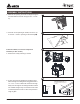
ASSEMBLY INSTRUCTIONS Install from above with suspension brackets (attic accessible) *ONLY IF UNABLE TO ATTACH DIRECTLY TO JOIST(S) 1. For joist spacing 16 in. - 24in., insert suspension bracket I ❸ and suspension bracket II ❹ into the bracket cover on the duct connector side and the back of the fan body ❶ .Install the suspension brackets to the joists with nails, and secure the suspension brackets to the fan body ❶ by using the short screws (provided).
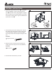
GRILLE INSTALLATION Attach grille ❷ by pinching mounting springs a and insert into the narrow rectangular slots in fan body. a 2 OPERATION Humidity Model: SIG110H Humidity preset control (SIG110H) or Delay time control (SIG80M, SIG80D & SIG110D) 4. Humidity control mode: Turn the POWER switch on to operate at humidity control mode - the LED indicator will be blue. When the ambient humidity is higher than the user-adjustable set-point, the fan will run at full speed, and the LED indicator is blue.
CARE AND MAINTENANCE See safety information before proceeding. Routine maintenance should be done at least once a year. • Never use solvents, thinner or harsh chemicals when cleaning the fan. • Do not allow water to enter the motor. 1 • Do not immerse metal parts in water. • Do not immerse resin parts in water over 140º Fahrenheit. Turn off power source. Review all safety precautions. 1. To remove grille ❷ , squeeze springs and pull down. 2. Wash and clean the grille ❷ in a sink and dry with a cloth.
TROUBLESHOOTING PROBLEM The fan is not turning on The fan seems louder than it should The fan is not clearing the room 12 POSSIBLE CAUSE CORRECTIVE ACTION 1. Power off 1. Make sure power supply is on. 2. Faulty switch 2. Test or replace switch. 3. Faulty wire connection 3. Check wire in switch box. 1. CFM too great 1. Be sure the CFM rating on the fan matches the size of your room. 2. Damper not working properly or damaged 2. Check damper to ensure it is opening and closing properly.
DIMENSIONS PRODUCT SPECIFICATIONS SPECIFICATIONS Model No. Voltage(V) Frequency Power @ Air Flow @ (Hz) 0.1”SP (W) 0.1”SP (CFM) Weight (lb.) Max.Current (amps) Note SIG80 120 60 8.7 80 10 0.30 Single Speed SIG80M 120 60 8.7 80 10 0.30 Motion Sensor SIG80D 120 60 8.7 80 10 0.30 Dual Speed SIG110 120 60 13.6 110 10 0.38 Single Speed SIG110H 120 60 13.6 110 10 0.38 Humidity Sensor SIG110D 120 60 13.6 110 10 0.
WARRANTY DELTA ELECTRONICS THREE YEAR LIMITED WARRANTY Delta Electronics Inc. (“Delta Electronics”) warrants to the original consumer purchaser in the USA that the Breez ventilation fan products will be free from defects in material or workmanship. This warranty is limited to three (3) years from the original date of purchase. Limitations and Exclusions 1. During the warranty period, a replacement for any defective product will be supplied free of charge for installation by the consumer.