
Combustible Ceiling Installation Instructions

Information is subject to change without notice or obligation. M-59988 Rev. C
Notes: Dimensions denoted by ( ) are in millimeters.
Ceiling Radiation Damper SMT-CRD
Combustible Ceiling Installation Instructions
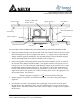
Gypsum
Damper Support 1
1
Finish Flooring
Vapor Barrier
Delta Breez SMT-CRD
Damper and Fan
Suspension Bracket
10-32 x 1/4” L
Screw
Grille
FIG. 1
For fan models: SMT130, SMT130H, SMT130M, SMT150, SMT150D and SMT150LED.
1. Install the radiation damper onto the inlet side of the fan so that the holes in the sleeve align
with mounting holes on the fan using the four #10-32 x ¼” long screws provided with the
damper assembly (general installation). The mounting flange of the fan should be aligned
with the mounting flange of the damper assembly (refer to Figure 1).
2. Prior to the gypsum ceiling being placed, install the Damper Supports 10-3/4” on center at
the location of the damper and fan assembly. The supports consist of two pieces of 2x4’s;
one piece is to be cut to the truss/joist height (Damper support1), the second is to be cut per
the following equation (Damper Support 2). The supports are to be flush mounted to the
bottom of the joist/truss and secured using at minimum 2” wood screws. Sizes for the fan
supports are based on the presence of a resilient channel, please refer to the appropriate UL
floor/ceiling design. For reference:
𝐷𝑎𝑚𝑝𝑒𝑟 𝑆𝑢𝑝𝑝𝑜𝑟𝑡 2 (𝐿𝑒𝑛𝑔𝑡ℎ) = 5
1
2
− 𝑅𝑒𝑠𝑖𝑙𝑖𝑒𝑛𝑡 𝐶ℎ𝑎𝑛𝑛𝑒𝑙 𝐻𝑒𝑖𝑔ℎ𝑡
3. Damper Support 2 is optional. An alternate Installation can be done using only Damper
Supports 1.
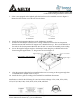
4. For a damper used with a fan equipped with a grille light, route the wire from the grille
through the notch on the damper frame. Use the supplied bracket to secure the wire to the
damper frame. Attach the bracket to the frame as seen in Figure 3 using one of the supplied
#8-18 screws.
Wood Joist/Wood Truss
Resilient Channel
Sub-Flooring
Damper Support 2