
Installation & Assembly
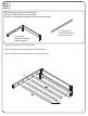
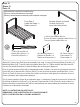


From Step 11
À partir de l’étape 11
Desde el paso 11
Parts and tools required to complete step
Pièces et outils nécessaires au montage
Piezas y herramientas necesarias para completar este paso
25
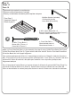
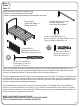
Step 12
Étape 12
Paso 12
M4 Allen Wrench (included)
Clé Allen M4 (inclus)
Llave Allen M4 (incluido)
X. M6 x 13mm Barrel Nut x 4
Écrous À Portée Cylindrique M6x13 mm x 4
Tuerca Cilíndrica M6x13mm x 4
T. M6 x 60 mm Bolt x 4
Boulon M6 x 60 mm x 4
Perno M6 x 60mm x 4
AA. Mending Plate x 2
Plaques de Renfort x 2
Placas de Corrección x 2
M. Center Leg x 2
Pied central x 2
Pata central x 2
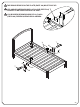
Attach (2) Center Legs (Part M) to the assembly from step 11 using (2) Mending Plates (Part AA), (4)
M6x60mm Bolts (Part T) and (4) M6x13mm Barrel Nuts (Part X). Tighten with the M4 Allen Wrench.
Use the Flat Head Screwdriver to hold the Barrel Nut in the proper alignment.
Fixer (2) pieds centraux (Pièce M) à l’assemblage monté à l’étape 11 à l'aide de (2) plaques de renfort
(Pièce AA), de (4) boulons M6 x 60 mm (Pièce T) et de (4) écrous à portée cylindrique M6 x 13 mm
(Pièce X). Serrer à l’aide de la clé Allen M4. Utiliser le tournevis à tête plate pour maintenir l’écrou à
portée cylindrique dans l'alignement adéquat.
Fije (2) patas centrales (Pieza M) a la pieza del paso 11 utilizando (2) placas de corrección (Pieza AA),
(4) pernos de M6x60 mm (Pieza T) y (4) tuercas Cilíndricas M6x13 mm (Pieza X). Apriete todos los
pernos utilizando la Llave Allen M4. Utilice el destornillador de cabeza plana para sostener la tuerca
Cilíndrica en la alineación adecuada.
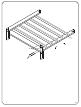
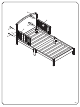
NOTE: ILLUSTRATION ON NEXT PAGE.
REMARQUE: VOIR ILLUSTRATION À LA PAGE SUIVANTE.
NOTA: ILUSTRACIÓN EN LA PÁGINA SIGUIENTE.