
Manual

GENERAL
The unit is manufactured, checked and supplied in
accordance with our published specification, and when
installed and used in normal or prescribed applications,
with the lid in place and within the parameters set for
mechanical and electrical performance, will not cause
danger or hazard to life or limb.
HEALTH AND SAFETY AT WORK ACT 1974
WARNINGS
1. THE USERS ATTENTION IS DRAWN TO THE
FACT THAT, WHEN THE UNIT IS ‘LIVE’ WITH
RESPECT TO ELECTRICAL OR PRESSURE
SUPPLIES, A HAZARD MAY EXIST IF THE
UNIT IS OPENED OR DISMANTLED.
2. UNITS MUST BE SELECTED AND INSTALLED
BY SUITABLY TRAINED AND QUALIFIED
PERSONNEL IN ACCORDANCE WITH
APPROPRIATE CODES OF PRACTICE SO
THAT THE POSSIBILITY OF FAILURE
RESULTING IN INJURY OR DAMAGE CAUSED
BY MISUSE OR MISAPPLICATION IS
AVOIDED.
OPERATING PRINCIPLES
Process pressure is sensed by a diaphragm that generates
a force proportional to the applied pressure. This force is
opposed by an adjustable spring, which at the point of
equilibrium permits movement of an operating rod that
actuates a switch or switches.
Note: Should the diaphragm fail the process will vent to
atmosphere via a control orifice without pressurising the
switch enclosure.
INSTALLATION
The instruments are designed to be mounted vertically with
the process connection underneath. However, mounting
up to 45° from the vertical in any plane is acceptable,
although a small calibration shift may occur. They can be
mounted either direct to process, or to a wall or panel
using the four mounting holes provided. Select the
mounting point so as to avoid excessive shock, vibration or
temperature fluctuation. Instruments should be mounted
to avoid excessive heat transfer from the process lines or
adjacent plant. To avoid undue stresses being imparted to
the instrument when wall / panel mounted, it is
recommended that a short length of flexible line be
installed between the instrument and process line.
Take care to select and install adaptors to the electrical
entry that do not reduce the enclosure degree of
protection.
NOTE: Enclosure Codes H & T for NEMA 4X use.
To ensure performance of enclosure, careful installation
and sealing of cable gland in situ is required.
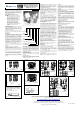
On enclosures H, R, T and U, remove the lid using an
appropriate tool if tight eg edge of spanner or metal rod (fig
2).
Use a spanner to support the process connection when
fitting the instrument. When fitting the instrument lid make
sure the ‘O’ ring is in good condition and fitted correctly.
On enclosures H, R, T, U, B remove the lid using an
appropriate tool if tight eg edge of a spanner or metal rod
(see fig 2).
WIRING Fig 1A Enclosures H, R, T, U, B
WIRING Fig 1B Enclosures W, A
PRODUCT CODE
ENCLOSURE
MODEL
ELECTRICAL ENTRY
MATERIAL OF WETTED PARTS
RANGE
SWITCHING OPTIONS
PROCESS CONNECTION
OPTIONS AND TREATMENTS
SPECIAL ENGINEERING
Wire in accordance with local and National codes. Use
cables no larger than 2.5 mm
2
(14 AWG). Deliver
electrical connection through a suitable cable gland that
will maintain the IP rating of the instrument. Insert bare
wires fully into the terminal block and tighten securely.
Keep wiring tails to a minimum and check that wires do not
interfere with the operating mechanism. Use the earthing /
grounding points provided.
CERTIFIED ENCLOSURES
All series S20 pressure switches can be supplied with
enclosures for use in hazardous areas to the following
standards:
Zone 1 (Div 1) IEC 79-1
BS 50014: 1997 + Amnds 1 and 2, EN 50018:2000
CENELEC. Codes ‘H’ for aluminium EEx d IIC T6, and ‘R’
for stainless steel EExd IIC T6.
WARNING: CHECK THE CONNECTION THREAD SIZE
AND SPECIFICATION ON THE UNIT TO AVOID MIS-
MATCHING WITH THE PROCESS CONNECTION
ADAPTOR. SEE DIGIT 11 OF PRODUCT CODE.
Special Conditions for Safe Use
The apparatus has a specified flame-path gap of 0.1
maximum associated with the push rod and bush
assembly passing through the enclosure wall, which is less
than the maximum permitted by the standard EN
50018:2000 to which the certification is issued. The user
shall ensure that, in service, this flame-path gap does not
exceed this value.
DIV 1 (NEC 500)
Class I Groups C and D, Class II Groups E, F and G.
Codes ‘T’ for aluminium and ‘U’ for stainless steel.
The above-mentioned enclosures are suitable for outdoor
use rated IP 66 / NEMA 4. Only operation, maintenance or
repair procedures either contained herein or approved by
Delta Controls may be used, to avoid rendering the
equipment unsafe in operation and/or nullifying the
Certification. NO MODIFICATIONS ARE PERMITTED.
Electrical Adaptors
Use only certified adaptors for Zone 1/Div 1.
1 or 2 electrical entries ISO to BS 3643 (1981) medium fit
6h up to M25 x 1.5 DIN 40430 (1971) up to Pg21. USAS
B2.1 (1968) gauging to clauses 36 & 37 up to 3/4" NPT.
BS conduit to BS31 (1940) table 'A' up to 1" BSP to BS21
(1985) standard threads only as clause 5.4 gauging to
clause 5.2 system 'A' up to Rp3/4 (medium fit or better).
Entry is normally from 1 side. Optional dual entry from
both sides. Cable entry holes are provided for the
accommodation of suitable BASEEFA certified flameproof
cable entry devices, with or without interposition of a
suitable BASEEFA certified flameproof thread adapter.
Unused entries are to be fitted with suitable BASEEFA
certified flameproof stopping plugs. Suitable flameproof
cable entry devices, thread adapters and stopping plugs
certified as equipment (not a component) under an EC
type examination certificate to directive 94/9/EC may also
be used in the manner specified above.
WARNING: IT IS A REQUIREMENT OF SAFETY THAT
AT LEAST 5 FULL THREADS ARE ENGAGED
BETWEEN THE ADAPTOR AND CONDUIT ENTRY.
References for Selection and Installation
BS EN 60079-14:1997 for Enclosure Codes H and R.
BS EN 50014:1997 + Amnds 1&2, EN 50018:2000 - Codes
H and R.
BS EN 60529:1992 IEC 529 IP RATING (Ingress
Protection)
NEC ARTICLE 500 for Enclosure Code T and U.
MAINTENANCE
Inspections should be carried out at quarterly to yearly
intervals depending upon operating conditions.
Isolate the unit from process and power and remove the
lid. Check all terminals for tightness. Check that cable
tails are not fouled or chafed. Check for internal
condensation. Rectify as necessary.
It is recommended that instruments used to provide an
alarm are operated periodically to ensure they are
functioning correctly.
If further maintenance is required seek advice from DELTA
CONTROLS before attempting repair or replacement of
parts.
CAUTION
Moving parts have been treated with a water repelling
lubricant before leaving the factory. Occasional inspection
and the application of a water repelling lubricant is
recommended to ensure moving parts remain free under
all conditions.
WARNING: DOES NOT APPLY TO OXYGEN SERVICE.
Zone 1 Enclosure (H, R, T, U, B)
Thread seal and contact surfaces must be lightly lubricated
using a non-setting non-corrosive grease compatible with
the lid seal. Do not use copper bearing grease. Screw on
lid hand tight making sure that mating surfaces of the lid
and enclosure are in contact. Re-tighten the lid lock
screw.
WARNING: IT IS A SAFETY REQUIREMENT THAT AT
LEAST 5 FULL THREADS ARE ENGAGED WHEN THE
UNIT IS IN OPERATION. NEVER OPERATE THE UNIT
UNLESS THIS CONDITION IS MET. DO NOT USE
GREASES OR LUBRICANTS NOT COMPATIBLE WITH
THE ENVIRONMENT OR PROCESS.
Weather-proof Enclosure (W)
If lid gasket is dried out or damaged, replace with new
greased gasket. Make sure gasket aligns correctly with
sealing faces.
Stainless Steel Weather-proof Enclosure (A)
Check gasket. If damaged, replace.
OPERATION
Pressure switches are supplied calibrated against falling
pressure unless otherwise specified. Set Point adjustment
refers to falling pressure. Switching differential is the
difference between the set point and the operating value
on rising pressure. For opening details see Figs 2, 6, 7, 8.
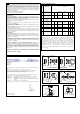
Set Point Adjustment: Models S21, S22 (Figs 3, 4)
1. Isolate the instrument from the process and power.
2. Loosen lid lock screw and remove the lid.
3. Retain in a safe place to avoid damage to threads.
4. Slacken the set point lock screw.
5. Rotate the set point adjuster screw as required. Rotate
clockwise to increase the set point and counter-clockwise
to decrease the set point.
6. Tighten the set point lock screw.
7. Replace the instrument lid (see maintenance).
Switching Differential Adjustment: Models S22 (Figs 3,
4, 5)
1. Isolate the instrument from process and power.
2. Loosen lid lock screw and remove the lid.
3. Retain in a safe place to avoid damage to threads.
4. Rotate the knurled plastic wheel on the microswitch to
adjust the switching differential. Rotate clockwise to
increase differential and counter-clockwise to reduce
differential.
Note: Rotating the knurled plastic wheel will alter the
operating value on rising pressure only.
5. Replace the instrument lid (see maintenance).
Note: For accurate setting, a suitable pressure gauge
must be used in conjunction with the above procedure. Do
not attempt to set the switch outside the scale limits.
Though the unit may be set anywhere within its operation
range, for optimum performance, it is good practice to
have a set point value between 25% and 75% of span.
ISSUE L 02/10
INSTALLATION, OPERATING AND
MAINTENANCE INSTRUCTIONS FOR
DIAPHRAGM ACTUATED SERIES S20
SOVEREIGN PRESSURE SWITCHES
(MODELS S21, S22, S24)
NO
COM
NC
NO
COM
NC
NO
COM
NC
BLUE
BROWN
RED
RED
BLUE
BROWN
RED
BLUE
BROWN
REAR FRONT
SPDT
2 x SPDT
NC = NORMALLY CLOSED
COM = COMMON
NO = NORMALLY OPEN
FIG 1A
BROWN
BLUE
RED
BROWN
BLUE
RED
RED
BROWN
BLUE
NC
COM
NO
NC
COM
NO
NC
COM
NO
NC = NORMALLY CLOSED
COM = COMMON
NO = NORMALLY OPEN
FRONT
SWITCH
SWITCH
REAR
2 x SPDT
SPDT
FIG 1B
300 (11.8)
MIN
7 (0.27)
18 (0.7)
R 3.5 (0.13)
FIG 2
ALL Dimensions mm (inches)
To remove lid on enclosures H, R, T, U, B
loosen lid locking device (see fig 8). Where lid
is tight use a flat bar, refer to recommended
sizes below. Material needs to be hard chrome
steel spanner grade.
The edge of a spanner may be used.
60 (2.36)
45 (1.77)
TYPE S24
Rc ¼
¼”NPT INT
TYPE S21/ 2
33 (1.29)
½”NPT INT
½”NPT EXT
¼”NPT INT
CONN
PROCESS
DIM A
½”NPT INT
Rc ¼
36 (1.41)
48 (1.88)
½”NPT EXT
(0.27)
(1.61)
DIM A
7
174 (6.85)
70
(2.75)
154 (6.06)
FIXING CENTRES
70 (2.75)
FIXING CENTRES
10 (0.39)
77 (3.03)
41
95 (3.74)
51 (2)
M4 EARTH SCREW
22 (0.86)
ELECTRICAL
ENTRY
PROCESS
CONNECTION
W ENCLOSURE
FIG 6
60 (2.36)
45 (1.77)
TYPE S24
Rc ¼
¼”NPT INT
TYPE S21/2
33 (1.29)
½”NPT INT
½”NPT EXT
¼”NPT INT
CONN
.
PROCESS
DIM A
½”NPT INT
Rc ¼
36 (1.41)
48 (1.88)
½”NPT EXT
(0.27)
DIM A
22 (0.86)
53 (2.08)
PROCESS
CONNECTION
45 (1.77)
103 (4.05)
154 (6.06)
FIXING CENTRES
174 (6.85)
70 (2.75)
FIXING
CENTRES
FIG 7
10 (0.39)
A ENCLOSURE
73 (2.87)
M4 EARTH SCREW
77 (3.03)
ELECTRICAL
ENTRY
7
60 (2.36)
45 (1.77)
TYPE S24
Rc ¼
¼”NPT INT
TYPE S21/ 2
33 (1.29)
½”NPT INT
½”NPT
EXT
¼”NPT INT
CONN
PROCESS
DIM A
½”NPT INT
Rc ¼
36 (1.41)
48 (1.88)
½”NPT EXT
(1.57)
FIXING
CENTRES
FIXING CENTRES
MOUNTING HOLES
8 mm (0.31) DIA
LID LOCKING SET SCREW (M4)
LOOSEN TO REMOVE LID
PROCESS CONNECTION
ELECTRICAL
ENTRY
FIG 8
H, R, T, U, B ENCLOSURE
ROTATE TO REMOVE
M5 EARTH
FACILITY
* ADD 12mm (0.47) FOR TYPE S21/2 RANGES CC, CD, CE ONLY SPACERS SUPPLIED LOOSE
*
DIM A
125 *(4.92)
56 *(2.2)
40
140 (5.51)
100 (3.93)
50 (1.96)
100 (3.93)
50
(1.96)
MAX
MI N
IN
ASE
NC
NC
NO
NO
COM
COM
FIG 3
SET POINT
LOCK
SET POINT
ADJUSTER
EARTH / GROUND
ENCLOSURES
H, R, T, U & B
MA
X
FIG 4
SET POINT
ADJUSTER
SET POINT
LOCK
EARTH / GROUND
ENCLOSURES W & A
ADJUST SWITCHING
DIFFERENTIAL
FIG. 4
FIG 5
ADJUSTABLE MICROSWITCH MODEL S22
In the interest of development and improvement Delta Controls Ltd, reserve the right to amend without notice,
details contained in this publication. No legal liability will be accepted by Delta Controls Ltd, for any errors,
omissions or amendments.
YOUR TRUSTED PARTNER IN PROCESS INSTRUMENTATION
DELTA CONTROLS LIMITED, ISLAND FARM AVENUE, WEST MOLESEY, SURREY KT8 2UZ
T +44 (0) 208 939 3511 F +44 (0) 208 783 1163 E sales@delta-controls.com W www.delta-controls.com
Stock No: 002522/S21
Registered Office Registered in England No 5369683
FIG.1
shows the state of electrical contacts at atmospheric pressure.
Note:-
products with ranges below atmospheric pressure have the wiring reversed
between the terminal block and the microswitch(es) to achieve this state.