
AC Motor Drive User Manual


Chapter 4 Parameters|
Revision June 2008, 04EE, SW--PW V1.11/CTL V2.11 4-121
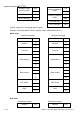
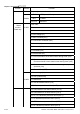
RTU mode:
Command message: Response message:
Address 01H Address 01H
Function 10H Function 10H
05H 05H Starting data
address
00H
Starting data address
00H
00H’ 00H Number of data
(count by word)
02H
Number of data
(count by word)
02H
Number of data
(count by byte)
04 CRC Check Low 41H
13H CRC Check High 04H The first data
content
88H
0FH The second data
content
A0H
CRC Check Low 4DH
CRC Check High D9H
3.4 Check sum
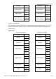
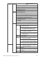
ASCII mode:
LRC (Longitudinal Redundancy Check) is calculated by summing up, module 256, the values
of the bytes from ADR1 to last data character then calculating the hexadecimal
representation of the 2’s-complement negation of the sum.
For example, reading 1 word from address 0401H of the AC drive with address 01H.
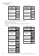
STX
‘:’
‘0’ Address 1
Address 0
‘1’
‘0’ Function 1
Function 0
‘3’
‘0’
‘4’
‘0’
Starting data address
‘1’
‘0’
‘0’
‘0’
Number of data
‘1’