
AC Motor Drive User Manual


Appendix D How to Use PLC Function|
D-12 Revision June 2008, 04EE, SW--PW V1.11/CTL V2.11
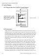
The explanation of command order:
1 LD X0
2 OR M0
3 AND X1
4 LD X3
AND M1
ORB
5 LD Y1
AND X4
6 LD T0
AND M3
ORB
7 ANB
8 OUT Y1
TMR T0 K10
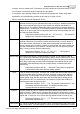
The detail explanation of basic structure of ladder diagram
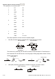
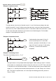
1. LD (LDI) command: give the command LD or LDI in the start of a block.
AND Block OR Block
LD command LD command
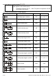
The structures of command LDP and LDF are similar to the command LD. The difference is
that command LDP and LDF will act in the rising-edge or falling-edge when contact is ON as
shown in the following.
X0
OFF
ON
OFF
Time
Falling-edge
X0
OFF
ON
OFF
Time
Rising-edge
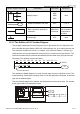
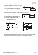
2. AND (ANI) command: single device connects to a device or a block in series.
AND comman
d
AND comman
d