
AC Motor Drive User Manual


Appendix D How to Use PLC Function|
Revision June 2008, 04EE, SW--PW V1.11/CTL V2.11 D-59
3. Please use rising-edge/falling-edge command, such as LDP/LDF, for the contact
condition. Please notice that error may occur when using contact A/B for the contact
condition.
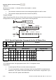
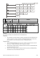
4. There are three input modes for high-speed counter in the following can be set by D1044.
A-B phase mode(4 times frequency )(D1044=0): user can input the A and B pulse for
counting. Make sure that
A
,
B
and GND are grounding.
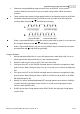
Pulse + signal mode(D1044=1): user can count by pulse input or signal. A is for pulse and
B is for signal. Make sure that
A
,
B
and GND are grounding.
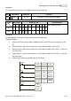
Pulse + flag mode(D1044=2): user can count by M1030. Only A is needed for this mode
and make sure that
A
, and GND are grounding.
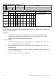
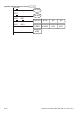
Program Example:
1. Assume that when M100=ON, it is set to A-B phase mode. When M101=ON, it is set to
pulse+signal mode. When M102=ON, it is set to pulse+flag mode.
2. M1030 is used to set to count up (OFF) and count down (ON).
3. If M0 goes from OFF to ON, DHSCS command starts to execute the comparison of high-
speed counter. When C235 goes from H’2 to H’3 or from H’4 to H’3, M3 will be always be
ON.
4. If M1 goes from OFF to ON, DHSCS command starts to execute the comparison of high-
speed counter. When C235 goes from H’1004F to H’10050 or from H’10051 to H’10050,
M2 will be always be ON.
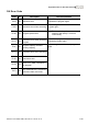
5. M1028: it is used to enable(ON)/disable(OFF) the high-speed counter function. M1029: it
is used to clear the high-speed counter. M1018: it is used to start high-speed counter
function. (when M1028 is ON).
6. D1025: the low word of high-speed counter C235. D1026: the high word of high-speed
counter C235.