
AC Motor Drive User Manual


Appendix D How to Use PLC Function|
Revision June 2008, 04EE, SW--PW V1.11/CTL V2.11 E-3
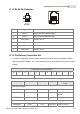
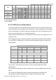
E.1.2 RJ-45 Pin Definition
8~1
8~1
socket
plug
PIN Signal Description
1 CAN_H CAN_H bus line (dominant high)
2 CAN_L CAN_L bus line (dominant low)
3 CAN_GND Ground / 0V /V-
4 SG+ 485 communication
5 SG- 485 communication
7 CAN_GND Ground / 0V /V-
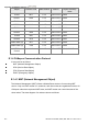
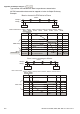
E.1.3 Pre-Defined Connection Set
To reduce configuration effort for simple networks, CANopen define a mandatory default
identifier allocation scheme. The 11-bit identifier structure in predefined connection is set as
follows:
COB Identifier (CAN Identifier)
10 9 8 7 6 5 4 3 2 1 0
Function Code Node Number
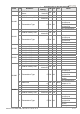
Object Function Code Node Number COB-ID Object Dictionary
Index
Broadcast messages
NMT 0000 - 0 -
SYNC 0001 - 0x80 0x1005, 0x1006,
0x1007
TIME STAMP 0010 - 0x100 0x1012, 0x1013
Point-to-point messages
Emergency 0001 1-127 0x81-0xFF 0x1014, 0x1015