Preface Thank you for choosing DELTA’s VFD-G Series for plastic molding and air compressors machinery. The VFD-G Series is manufactured with high-quality components and materials and incorporates the latest microprocessor technology available. This manual is to be used for the installation, parameter setting, troubleshooting, and daily maintenance of the AC motor drive. To guarantee safe operation of the equipment, read the following safety guidelines before connecting power to the AC motor drive.
WARNING! 1. DO NOT use Hi-pot test for internal components. The semi-conductor used in the AC motor drive is easily damaged by high-pressure. 2. There are highly sensitive MOS components on the printed circuit boards. These components are especially sensitive to static electricity. To prevent damage to these components, do not touch these components or the circuit boards with metal objects or your bare hands. 3. Only qualified persons are allowed to install, wire and maintain AC motor drives.
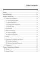
Table of Contents Preface ............................................................................................................. i Table of Contents .......................................................................................... iii Chapter 1 Introduction ................................................................................ 1-3 1.1 Receiving and Inspection ................................................................... 1-3 1.1.1 Nameplate Information........................
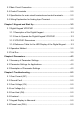
2.3 Main Circuit Connection......................................................................2-3 2.4 Control Terminals ...............................................................................2-3 2.5 Specification for main circuit terminals and control terminals..............2-3 2.6 Wiring Explanation for Analog Input Terminal.....................................2-3 Chapter 3 Keypad and Start Up ..................................................................3-3 3.1 Digital Keypad VFD-PU01 .....
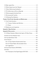
5.9 Motor cannot Run............................................................................... 5-3 5.10 Motor Speed cannot be Changed..................................................... 5-3 5.11 Motor Stalls during Acceleration....................................................... 5-3 5.12 The Motor does not Run as Expected .............................................. 5-3 5.13 Electromagnetic/Induction Noise ...................................................... 5-3 5.14 Environmental Condition ...
B.6.2 Explanation of Display Message .................................................B-3 B.6.3 PU06 Operation Flow Chart ........................................................B-3 Appendix C How to Select the Right AC Motor Drive .............................. C-3 C.1 Capacity Formulas ............................................................................ C-3 C.2 General Precaution ........................................................................... C-3 C.3 How to Choose a Suitable Motor.....
Chapter 1 Introduction 1.1 Receiving and Inspection This VFD-G AC motor drive has gone through rigorous quality control tests at the factory before shipment. After receiving the AC motor drive, please check for the following: Check to make sure that the package includes an AC motor drive, the User Manual/Quick Start and CD, dust covers and rubber bushings. Inspect the unit to assure it was not damaged during shipment.
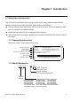
Chapter 1 Introduction| 1.1.3 Series Number Explanation 075F43AG4 T 7 01 0001 Production number 460V 3-PHASE 10HP(7.5kW) Production model If the nameplate information does not correspond to your purchase order or if there are any problems, please contact your distributor. 1.1.4 Drive Frames Frame Power Range Models 7.5-20HP (5.5-15kW) VFD055F43B-G, VFD075F43B-G, VFD110F43A-G, VFD150F43A-G D 25-40HP (18.
Chapter 1 Introduction| 50-125HP/37-90kW(Frame E, E1) 150-215HP/110-160kW(Frame G) 250-300HP/185-220kW(Frame H) Revision July 2008, EG03, SW V1.
Chapter 1 Introduction| 1.3 Remove Instructions 1.3.1 Remove Keypad 1-4 7.5-20HP/5.5-15kW(Frame C) 25-40HP/18.5-30kW(Frame D) 50-125HP/37-90kW(Frame E, E1) 150-215HP/110-160kW(Frame G) Revision July 2008, EG03, SW V1.
Chapter 1 Introduction| 250-300HP/185-220kW(Frame H) 1.3.2 Remove Front Cover 7.5-20HP/5.5-15kW(Frame C) Revision July 2008, EG03, SW V1.06 25-40HP/18.
Chapter 1 Introduction| 50-125HP/37-90kW(Frame E, E1) 150-215HP/110-160kW(Frame G) 250-300HP/185-220kW(Frame H) 1-6 Revision July 2008, EG03, SW V1.
Chapter 1 Introduction| 1.4 Lifting Please carry only fully assembled AC motor drives as shown in the following. For 50-125HP (Frame E, E1) Step 1 Step 2 Step 3 Step 4 Revision July 2008, EG03, SW V1.
Chapter 1 Introduction| For 150-215HP (Frame G) 1-8 Step 1 Step 2 Step 3 Step 4 Revision July 2008, EG03, SW V1.
Chapter 1 Introduction| For 250-300HP (Frame H) Step 1 Step 2 Step 3 Step 4 Revision July 2008, EG03, SW V1.
Chapter 1 Introduction| 1.5 Preparation for Installation and Wiring 1.5.1 Ambient Conditions Install the AC motor drive in an environment with the following conditions: Air Temperature: -10 ~ +40°C (14 ~ 104°F) Relative Humidity: <90%, no condensation allowed Atmosphere pressure: Installation Site Altitude: Operation Storage Transportation <1000m Vibration: <20Hz: 9.80 m/s2 (1G) max 20 ~ 50Hz: 5.88 m/s2 (0.
Chapter 1 Introduction| CAUTION! 1. Operating, storing or transporting the AC motor drive outside these conditions may cause damage to the AC motor drive. 2. 3. Failure to observe these precautions may void the warranty! Mount the AC motor drive vertically on a flat vertical surface object by screws. Other directions are not allowed. 4. The AC motor drive will generate heat during operation. Allow sufficient space around the unit for heat dissipation. 5.
Chapter 1 Introduction| 1.6 Dimensions W W1 D H H1 F Unit: mm [inch] Frame W W1 H H1 D F C 200.0 [7.88] 185.6 [7.31] 323.0 [12.72] 303.0 [11.93] 183.2 [7.22] 7.0 [0.28] D 250.0 [9.84] 226.0 [8.90] 403.8 [15.90] 384.0 [15.12] 205.4 [8.08] 10.0 [0.39] NOTE Frame C: VFD055F43B-G, VFD075F43B-G, VFD110F43A-G, VFD150F43A-G Frame D: VFD185F43A-G, VFD220F43A-G, VFD300F43A-G W D W1 H2 H H1 F Unit: mm [inch] Frame W W1 H H1 H2 D F E 370.0[14.57] 335.0[13.19] 589.0[23.
Chapter 1 Introduction| W W1 D H2 H1 H RF Unit: mm [inch] Frame W W1 H H1 H2 D F G 425.0[16.73] 381.0[15.00] 850.0[33.46] 819.5[32.26] 764.0[30.08] 264.0[10.39] 6.5[0.26] NOTE Frame G: VFD1100F43C-G, VFD1320F43A-G, VFD1600F43A-G Unit: mm [inch] Frame W W1 H H1 H2 D1 F H 547.0[21.54] 480.0[18.90] 1150.0[45.28] 1119.0[44.06] 1357.6[53.45] 360.0[14.17] 13.0[0.51] NOTE Frame H: VFD1850F43A-G, VFD2200F43A-G Revision July 2008, EG03, SW V1.
Chapter 1 Introduction| This page intentionally left blank. 1-14 Revision July 2008, EG03, SW V1.
Chapter 2 Installation and Wiring After removing the front cover, check if the power and control terminals are clear. Be sure to observe the following precautions when wiring. General Wiring Information Applicable Codes All VFD-G series are Underwriters Laboratories, Inc. (UL) and Canadian Underwriters Laboratories (cUL) listed, and therefore comply with the requirements of the National Electrical Code (NEC) and the Canadian Electrical Code (CEC).
Chapter 2 Installation and Wiring| DANGER! 1. A charge may still remain in the DC bus capacitors with hazardous voltages even if the power has been turned off. To prevent personal injury, please ensure that the power is turned off and wait ten minutes for the capacitors to discharge to safe voltage levels before opening the AC motor drive. 2. Only qualified personnel familiar with AC motor drives is allowed to perform installation, wiring and commissioning. 3.
Chapter 2 Installation and Wiring| For 460V series, 20hp and below DC Reactor (O pti onal) Br ak e Resistor (O pti onal) BR Jumper NFB +1 +2/B1 MC R/L1 S/L2 T /L3 R/L1 S/L2 B2 VFD-G T /L3 NFB U /T1 V/T2 W/T 3 Motor IM 3~ SA Recommended C ircui t when power s upply is turned O FF by a fault output F ac tor y Setting RB1 ON MC E.F. F WD/ST OP REV/STO P Multi-s tep1 Multi-s tep2 Multi-s tep3 Multi-s tep4 Digital Si gnal Common *Don't apply the mains voltage dir ectly to abov e terminals.
Chapter 2 Installation and Wiring| Br ak e Unit (O ptional ) For 460V series, 25hp and above DC Reactor (O pti onal) V FDB B1 Br ak e R esistor (O pti onal) P N B2 Jumper NFB S/L2 T /L3 +1 MC R/L1 R/L1 S/L2 - +2 VFD-G T /L3 NFB U /T1 V/T2 W/T 3 Motor IM 3~ SA Recommended C ircui t when power s upply is turned O FF by a fault output F ac tor y Setting RB1 ON MC E.F.
Chapter 2 Installation and Wiring| Wiring for SINK mode and SOURCE mode SINK Mode E.F. FWD/STOP REV/STOP Multi-step1 Multi-step2 Multi-step3 Multi-step4 Digital Signal Common *Don't apply the mains voltage directly to above terminals SOURCE Mode Sink Sw1 Source +24V EF FWD REV MI1 MI2 MI3 MI4 DCM +24V E.F. FWD/STOP REV/STOP Multi-step1 Multi-step2 Multi-step3 Multi-step4 *Don't apply the mains voltage directly to above terminals EF FWD REV MI1 MI2 MI3 MI4 DCM CAUTION! 1. 2.
Chapter 2 Installation and Wiring| 7. With long motor cables, high capacitive switching current peaks can cause over-current, high leakage current or lower current readout accuracy. To prevent this, the motor cable should be less than 20m for 3.7kW models and below. And the cable should be less than 50m for 5.5kW models and above. For longer motor cables use an AC output reactor. 8. The AC motor drive, electric welding machine and the greater horsepower motor should be grounded separately. 9. 10.
Chapter 2 Installation and Wiring| 2.2 External Wiring Items Power supply FUSE/NFB Fuse/NFB (Optional) There may be an inrush current during power up. Please check the chart of Appendix B and select the correct fuse with rated current. Use of an NFB is optional. Magnetic contactor Magnetic contactor (Optional) Please do not use a Magnetic contactor as the I/O switch of the AC motor drive, as it will reduce the operating life cycle of the AC drive.
Chapter 2 Installation and Wiring| 2.
Chapter 2 Installation and Wiring| CAUTION! Mains power terminals (R/L1, S/L2, T/L3) Connect these terminals (R/L1, S/L2, T/L3) via a non-fuse breaker or earth leakage breaker to 3phase AC power (some models to 1-phase AC power) for circuit protection. It is unnecessary to consider phase-sequence. It is recommended to add a magnetic contactor (MC) in the power input wiring to cut off power quickly and reduce malfunction when activating the protection function of AC motor drives.
Chapter 2 Installation and Wiring| To improve the power factor and reduce harmonics, connect a DC reactor between terminals [+1, +2(+2/B1)]. Please remove the jumper before connecting the DC reactor. Models of 18.5kW~160kW have a built-in DC reactor; models of 185kW~220kW have a built-in AC reactor. Terminals [+2/B1, B2] for connecting brake resistor and terminals [+2(+2/B1), -] for connecting external brake unit BR Bra ke Resistor (Opt io nal) Ref er to Appen dix B for details.
Chapter 2 Installation and Wiring| 2.4 Control Terminals Terminal Symbol Terminal Function Factory Settings FWD Forward-Stop command FWD-DCM: ON: Run in FWD direction OFF: Ramp to stop REV Reverse-Stop command REV-DCM: ON: Run in REV direction OFF: Ramp to stop EF External fault EF-DCM: ON: External Fault. Display “EF” and coast/ramp to stop OFF: No fault MI1 Multi-function Input 1 MI2 Multi-function Input 2 MI3 Multi-function Input 3 MI4 Multi-function Input 4 MI1~MI4-DCM: Refer to Pr.
Chapter 2 Installation and Wiring| Terminal Symbol Terminal Function Factory Settings +12V/ACM Potentiometer power source +12Vdc 20mA (Variable Resistor: 3~5KΩ) AI1 Analog voltage/current Input 0~10V/0~1A correspond to 0~Max. operation frequency Resolution: 10 bits Function: Pr.04-05 ~ Pr.04-25 AI2 Analog voltage/current Input 0~10V/0~1A correspond to 0~Max. operation frequency Resolution: 10 bits Funciton: Pr.04-05 ~ Pr.
Chapter 2 Installation and Wiring| General Keep control wiring as far away as possible from the power wiring and in separate conduits to avoid interference. If necessary let them cross only at 90º angle. The AC motor drive control wiring should be properly installed and not touch any live power wiring or terminals. NOTE If a filter is required for reducing EMI (Electro Magnetic Interference), install it as close as possible to AC drive. EMI can also be reduced by lowering the Carrier Frequency.
Chapter 2 Installation and Wiring| 2.5 Specification for main circuit terminals and control terminals 7.5 HP to 20 HP (VFD055F43B-G, VFD075F43B-G, VFD110F43A-G, VFD150F43A-G) POWER IM 3 MOTOR Control Terminal Torque: 4Kgf-cm (3 in-lbf) Wire: 12-24 AWG Power Terminal Torque: 30Kgf-cm (26 in-lbf) Wire: 12-8 AWG Wire Type: Stranded copper only, 75° C NOTE: If wiring of the terminal utilizes the wire with a 6AWG-diameter, it is thus necessary to use the Recognized Ring Terminal to conduct a proper wiring.
Chapter 2 Installation and Wiring| 25 HP to 40 HP (VFD185F43A-G, VFD220F43A-G, VFD300F43A-G) R/L1 S/L2 T/L3 +1 POWER +2 DC (+) - DC ( - ) V/T2 W/T3 IM 3 MOTOR Control Terminal Torque: 4Kgf-cm (3 in-lbf) Wire: 12-24 AWG Power Terminal Torque: 30Kgf-cm (26 in-lbf) Wire: 8-2 AWG Wire Type: Stranded copper only, 75° C NOTE: If wiring of the terminal utilizes the wire with a 1AWG-diameter, it is thus necessary to use the Recognized Ring Terminal to conduct a proper wiring.
Chapter 2 Installation and Wiring| 50 HP to 60 HP (VFD370F43A-G, VFD450F43A-G) POWER ALARM CHARGE R/L1 S/L2 T/L3 POWER +1 +2 - U/T1 V/T2 2/T3 IM 3 MOTOR Control Terminal Torque: 4Kgf-cm (3 in-lbf) Wire: 12-24 AWG Power Terminal Torque: 57kgf-cm (49.5 in-lbf) min. Wire: VFD370F43A-G: 3AWG VFD450F43A-G: 2AWG Wire Type: Stranded copper only, 75° C 2-16 Revision July 2008, EG03, SW V1.
Chapter 2 Installation and Wiring| 75 HP to 125 HP (VFD550F43A-G, VFD750F43A-G, VFD900F43C-G) POWER ALARM CHARGE R/L1 S/L2 T/L3 POWER +1 +2 Screw Torque: 200kgf-cm (173in-lbf) U/T1 V/T2 W/T3 IM 3 MOTOR Control Terminal Torque: 4Kgf-cm (3 in-lbf) Wire: 12-24 AWG Power Terminal Torque: 200kgf-cm (173 in-lbf) Wire: VFD550F43A-G: 1/0-4/0 AWG VFD750F43A-G: 3/0-4/0 AWG VFD900F43C-G: 4/0 AWG Wire Type: Stranded copper only, 75°C Revision July 2008, EG03, SW V1.
Chapter 2 Installation and Wiring| 150 HP to 215 HP (VFD1100F43C-G, VFD1320F43A-G, VFD1600F43A-G) R/L1 S/L2 T/L3 POWER Control Terminal Torque: 4Kgf-cm (3 in-lbf) Wire: 12-24 AWG +1 +2 U/T1 V/T2 W/T3 IM DC(+) DC(-) MOTOR 3 NOTE: It needs following additional terminal when wiring. The additional terminal dimension should comply with the following figure.
Chapter 2 Installation and Wiring| 250 HP to 300 HP (VFD1850F43A-G, VFD2200F43A-G) R/L1 S/L2 T/L3 POWER Control Terminal Torque: 4Kgf-cm (3 in-lbf) Wire: 12-24 AWG + - DC (+) DC (-) U/T1 V/T2 W/T3 NOTE: It needs following additional terminal when wiring, and add insulation sheath on position where following figure shows. Power Terminal Torque: 408kgf-cm (354 in-lbf) Wire: 500 MCM (max) Wire Type: Stranded copper only, 75°C Revision July 2008, EG03, SW V1.
Chapter 2 Installation and Wiring| 2.6 Wiring Explanation for Analog Input Terminal When using analog input, please pay attention to the jumper on the control board. Whether the jumper is cut off or not is determined by analog input type (voltage or current). See the figure below and refer to the following explanation for more details. 2-20 Revision July 2008, EG03, SW V1.
Chapter 2 Installation and Wiring| 1. When using analog current input (0~1A), please plug into the left two pins (See the red mark), and make sure the jumper is connected well (See what the following yellow arrows point at). 2. When using analog voltage input (0~10V), please transfer to the right two pins (See the red mark), and cut off the jumper (See what the following yellow arrows point at). Revision July 2008, EG03, SW V1.
Chapter 2 Installation and Wiring| This page intentionally left blank. 2-22 Revision July 2008, EG03, SW V1.
Chapter 3 Keypad and Start Up 3.1 Digital Keypad VFD-PU01 3.1.1 Description of the Digital Keypad F H U LED Display Display frequency, current, voltage and error, etc. VFD-PU01 Part Number Status Display Display the driver's current status JOG By pressing JOG key. Initiates jog operation. MODE Changes between different JOG display mode. Left key moves cursor to the left UP and DOWN Key Sets the parameter number and changes the numerical data, such as Master Frequency.
Chapter 3 Keypad and Start Up| Display Message Descriptions Display “End” for approximately 1 second if input has been accepted. After a parameter value has been set, the new value is automatically stored in memory. To modify an entry, use the or keys. Display “Err”, if the input is invalid. 3.1.2 How to Operate the Digital Keypad VFD-PU01 Selecting mode START F F F H U F H H H U U U MODE MODE F H U MODE MODE MODE GO START Note:In the selection mode, press to set the parameters.
Chapter 3 Keypad and Start Up| 3.1.3 VFD-PU01 Dimensions 110.0 [4.33] PROG DATA 8] .5 77.0 [3.03] [1 .0 40 MODE M4* 0.7(2X) ? JOG 44.0 [1.73] 97.0 [3.82] 19.0 [0.75] 73.0 [2.87] STOP 6.5 [0.26] RUN Unit: mm [inch] 3.1.
Chapter 3 Keypad and Start Up| 3.2 Operation Method The operation method can be set via communication, digital keypad and control terminals. Please choose a suitable method depending on application and operation rule. Operation Method Frequency Source Operation Command Source Refer to the communication address Operate from the 2001H setting for details. communication (Parameter setting: Pr.02-00=03) Refer to the communication address 2000H setting for details. (Parameter setting: Pr.
Chapter 3 Keypad and Start Up| 3.3 Trial Run you can perform a trial run by using digital keypad with the following steps. The factory setting of the operation source is from the keypad (Pr.02-01=00). 1. After applying power, verify that LED “F” is on and the display shows 60.00Hz. 2. Setting frequency to about 5Hz by using 3. Pressing RUN key for forward running. And if you want to change to reverse running, you should press please press 4. key. STOP RESET key in F H U page.
Chapter 3 Keypad and Start Up| This page intentionally left blank. 3-6 Revision July 2008, EG03, SW V1.
Chapter 4 Parameters The VFD-G parameters are divided into 10 groups by property for easy setting. In most applications, the user can finish all parameter settings before start-up without the need for re-adjustment during operation.
Chapter 4 Parameters| 4.1 Summary of Parameter Settings : The parameter can be set during operation.
Chapter 4 Parameters| Parameter Functions Settings Factory Customer Setting 43: HPF3 (OC hardware error) 44: HPF4 (OV hardware error) 45: CF3.3 (U-phase error) 46: CF3.4 (V-phase error) 47: CF3.5 (W-phase error) 48: CF3.6 (OV or LV) 49: CF3.7 (Isum error) 50: CF3.
Chapter 4 Parameters| Parameter Functions Settings Factory Customer Setting 00-13 User Target Value (High bit) uH 0-9999 Read only Read 00-14 PLC Time Read only Read 00-15 Output Reactive Power (KVAR) Read only Read Group 1 Basic Parameters Parameter 4-4 Functions Settings Factory Customer Setting 01-00 Maximum Output Frequency 50.00~160.00Hz 60.00 01-01 Maximum Voltage Frequency (Base Frequency) 0.10~160.00 Hz 60.00 01-02 Maximum Output Voltage 0.2V ~ 510.0V 440.
Chapter 4 Parameters| Parameter Functions Settings Factory Customer Setting 01-17 JOG Acceleration Time 0.1~3600.0 Sec 10.0/ 60.0 01-18 JOG Deceleration Time 0.1~3600.0 Sec 10.0/ 60.0 JOG Frequency 0.0 Hz~160.00 Hz 6.00 01-20 01-19 S Curve Delay Time in Accel 0.00~2.50sec 0.00 01-21 S Curve Delay Time in Decel 0.00~2.50sec 0.00 Modulation Index 0.90~1.20 1.00 01-22 01-23 Accel/Decel Time Unit 00: Unit is 1 Sec 01: Unit is 0.1 Sec 02: Unit is 0.
Chapter 4 Parameters| Parameter 4-6 Functions Factory Customer Setting Settings 02-04 Forward/Reverse Enable 00: Forward enabled 01: Reverse disabled 02: Forward disabled 00 02-05 2-wire/3-wire Operation Control Modes 00: 2-wire: FWD/STOP, REV/STOP 01: 2-wire: FWD/REV, RUN/STOP 02: 3-wire operation 00 02-06 Line Start Lockout 00: Disabled 01: Enabled 01 02-07 Reserved 02-08 Start-up Display Selection Bit0~1: 00 = F LED 01 = H LED 10 = U LED (special display) 11 = Fwd / Rev Bit2: 0 = Fw
Chapter 4 Parameters| Group 3 Output Function Parameters Parameter Functions Settings 01 03-00 Multi-function Output Terminal 1 (Relay) 03-01 Reserved 03-02 Master Frequency Attained 1 0.00~160.00 Hz 0.00 03-03 Master Frequency Attained 2 0.00~160.00 Hz 0.00 03-04 DC Fan Control 00: Fan runs on power up. 01: Fan begins upon a RUN command. Fan stops 1 minute after a STOP command. 02: Fan begins upon a RUN command. Fan stops after a STOP command 03: Fan is controlled by temperature.
Chapter 4 Parameters| Group 4 Input Function Parameters Parameter Factory Customer Setting Settings 00: disabled 01: Multi-Speed terminal 1 02: Multi-Speed terminal 2 03: Multi-Speed terminal 3 04: Multi-Speed terminal 4 05: Reset (NO) 06: Reset (NC) 07: Jog operation (JOG) 08: Accel/Decel disabled 09: 1st and 2nd Accel/Decel selection 10: 3rd and 4th Accel/Decel selection 11: B.B. (NO) input 12: B.B.
Chapter 4 Parameters| Parameter Functions Settings Factory Customer Setting 04-14 2nd AI1 Gain 0.0~100.0% 100.0 04-15 3rd AI1 Gain 0.0~100.0% 100.0 04-16 4th AI1 Gain 0.0~100.0% 100.0 04-17 5th AI1 Gain 0.0~100.0% 100.0 04-18 1st AI2 Gain 0.0~100.0% 100.0 04-19 2nd AI2 Gain 0.0~100.0% 100.0 04-20 3rd AI2 Gain 0.0~100.0% 100.0 04-21 4th AI2 Gain 0.0~100.0% 100.0 04-22 5th AI2 Gain 0.0~100.0% 100.0 04-23 Analog Input Delay AI1 0.00~10.00 Sec 0.
Chapter 4 Parameters| Group 5 Multi-step Speed Parameters Parameter Functions Factory Customer Setting Settings 05-00 1st Step Speed Frequency 0.00~160.00 Hz 0.00 05-01 2nd Step Speed Frequency 0.00~160.00 Hz 0.00 05-02 3rd Step Speed Frequency 0.00~160.00 Hz 0.00 05-03 4th Step Speed Frequency 0.00~160.00 Hz 0.00 05-04 5th Step Speed Frequency 0.00~160.00 Hz 0.00 05-05 6th Step Speed Frequency 0.00~160.00 Hz 0.00 05-06 7th Step Speed Frequency 0.00~160.00 Hz 0.
Chapter 4 Parameters| Parameter Functions Settings Factory Customer Setting 05-20 Time Duration Step 4 0.0 to 65500 Sec / 0.0~6550.0 Sec 0.0 05-21 Time Duration Step 5 0.0 to 65500 Sec / 0.0~6550.0 Sec 0.0 05-22 Time Duration Step 6 0.0 to 65500 Sec / 0.0~6550.0 Sec 0.0 05-23 Time Duration Step 7 0.0 to 65500 Sec / 0.0~6550.0 Sec 0.0 05-24 Time Duration Step 8 0.0 to 65500 Sec / 0.0~6550.0 Sec 0.0 05-25 Time Duration Step 9 0.0 to 65500 Sec / 0.0~6550.0 Sec 0.
Chapter 4 Parameters| Parameter Functions Factory Customer Setting Settings 06-06 Electronic Thermal Relay Selection 00: Operate disabled. 01: Operate with a standard motor. 02: Operate with a special motor. 02 06-07 Electronic Thermal Characteristic 30~600 Sec 60 06-08 Low Current Detection 00~100% (00 disabled) Level 06-09 Low Current Detection 0.1~ 3600.
Chapter 4 Parameters| Parameter Functions Settings Factory Customer Setting 31: FF12 (Fan 1, 2 Fault) 32: FF13 (Fan 1, 3 Fault) 33: FF23 (Fan 2, 3 Fault) 34: Fv (Gate Drive Low Voltage Protect) 35~40: Reserved 41: HPF1 (GFF hardware error) 42: HPF2 (CC,OC hardware error) 43: HPF3 (OC hardware error) 44: HPF4 (OV hardware error) 45: CF3.3 (U-phase error) 46: CF3.4 (V-phase error) 47: CF3.5 (W-phase error) 48: CF3.6 (OV or LV) 49: CF3.7 (Isum error) 50: CF3.
Chapter 4 Parameters| Parameter Functions Settings Factory Customer Setting 07-08 Calculate Total Running Time of the Motor (Min) 00 to 1439 Min 00 07-09 Calculate Total Running Time of the Motor (Day) 00 to 65535 Day 00 07-10 Electric Bill for One Time Read Only 07-11 Accumulated Electric Bill (per currency unit) Read Only 07-12 Accumulated Electric Bill (per 104 currency unit) Read Only Electric Rate (per currency unit) 0.01 to 655.35 07-13 Read Read Read 0.
Chapter 4 Parameters| Parameter Functions Settings Factory Customer Setting 08-11 Operation Frequency Inhibition 1 UP 0.00~160.00 Hz 0.00 08-12 Operation Frequency Inhibition 1 DOWN 0.00~160.00 Hz 0.00 08-13 Operation Frequency Inhibition 2 UP 0.00~160.00 Hz 0.00 08-14 Operation Frequency Inhibition 2 DOWN 0.00~160.00 Hz 0.00 08-15 Operation Frequency Inhibition 3 UP 0.00~160.00 Hz 0.00 08-16 Operation Frequency Inhibition 3 DOWN 0.00~160.00 Hz 0.
Chapter 4 Parameters| Parameter Factory Customer Setting Settings Even/Odd Parity and 00: None parity + 2 stop bit Stopping Parity Setting 01: Even parity + 2 stop bit 02: Odd parity + 2 stop bit 03: None parity + 1 stop bit 04: Even parity + 1 stop bit 05: Odd parity + 1 stop bit 00 09-06 Communication Bit0~1: 00: Disable Operation Command 1 01: Stop 10: Start-up 11: JOG start-up Bit2~3: Reserved Bit4~5: 00: No function 01: FWD command 10: REV command 11: Change direction command Bit6~7: 00: 1st ste
Chapter 4 Parameters| Group 10 PID Control Parameters Parameter Functions Settings Factory Customer Setting 10-00 Input Terminal for PID Feedback 00: Disabled 01: Input via AI1 02: Input via AI2 03: Input via External Reference 00 10-01 PID Control Detection Signal Reference 1.0-6550.0 10-02 PID Feedback Control 00: Normal (Err=SP-FB) Method 01: Inverse (Err=FB-SP) 10-03 Proportional Gain (P) 0.0~10.0 1.0 10-04 Integral Time (I) 0.00~100.00 Sec 1.00 1000.
Chapter 4 Parameters| 4.2 Parameter Settings for Applications Speed Search Applications Windmill, winding machine, fan and all inertia load Purpose Restart freerunning motor Functions Before the free-running motor is completely stopped, it can be restarted without detecting motor speed. The AC motor drive will auto search motor speed and will accelerate when its speed is the same as the motor speed.
Chapter 4 Parameters| Overheat Warning Applications Air conditioner Functions Related Parameters When the AC motor drive overheats, it uses a thermal sensor to generate a overheat warning.
Chapter 4 Parameters| Emergency Stop by DC Brake Applications High-speed rotors Purpose Emergency stop without brake resistor Functions AC motor drive can use DC brake for emergency stop when a quick stop is needed without brake resistor. When used often, take motor cooling into consideration.
Chapter 4 Parameters| Output Signal during Running Applications General application Purpose Functions Signal available to stop braking when Provide a signal for the AC motor drive is running. (This running status signal will disappear when the AC motor drive is free-running.) Related Parameters 03-00 Output Signal in Zero Speed Applications General application Purpose Functions When the output frequency is lower Provide a signal for than the min.
Chapter 4 Parameters| Output Signal for Base Block Applications General application Purpose Functions When executing Base Block, a signal Provide a signal for is sent by an external system or running status control wiring. Related Parameters 03-00 Overheat Warning for Heat Sink Applications General application Purpose For safety Functions When heat sink is overheated, it will send a signal by an external system or control wiring.
Chapter 4 Parameters| 4.3 Description of Parameter Settings Group 0: User Parameters : This parameter can be set during operation. 00 - 00 Software Version Factory setting: Read Only This parameter displays the software version of AC drive. 00 - 01 AC Drive Status Indication 1 Factory setting: Read Only This parameter displays the AC drive status.
Chapter 4 Parameters| Code 22 AC Drive Status Explanation PHL (phase loss) Input power lacks phase. 3-phase input power is unbalance and exceeds specification. 23 Lc (Low Current) Low current detection during operation. 24 FbL(Feedback Loss) Feedback signal is abnormal.
Chapter 4 Parameters| Bit 8: Master frequency source via communication interface Bit 9: Master frequency source via analog Bit10: Running command via communication interface Bit11: Parameter locked Bit12~15: Reserved 00 - 03 Frequency Setting (F) or Closed Loop Control Setting Point Factory setting: Read Only This parameter displays the frequency command set by the user. 00 - 04 Output Frequency (H) Factory setting: Read Only This parameter displays actual output frequency of the AC drive.
Chapter 4 Parameters| 00 - 10 Feedback Signal Actual Value Factory setting: Read Only This parameter displays feedback signal value. 00 - 11 Feedback Signal (%) Factory setting: Read Only This parameter displays feedback signal value(%). 00 - 12 User Target Value (Low bit) uL 0-99.99 Factory setting: Read Only 00 - 13 User Target Value (High bit) uH 0-9999 Factory setting: Read Only User Target Value = Actual output frequency (0-04) × User Defined Multiplier (02-10).
Chapter 4 Parameters| Group 1: Basic Parameters 01 - 00 Maximum Output Frequency Settings 50.00~160.00Hz Factory Setting: 60.00 This parameter determines the AC drives maximum output frequency. All master frequency commands set by the keypad or analog inputs are limited by this parameter. The analog commands (ACI1 and ACI2) may be scaled to correspond to the output frequency range. (Please refer to 04-05~04-12.) 01 - 01 Maximum Voltage Frequency (Base Frequency) Settings 0.10~160.
Chapter 4 Parameters| 01 - 04 Mid-point Voltage Settings 0.2V~510.0V Factory Setting: 11.0 This parameter sets the Mid-point Voltage of the V/F curve. This parameter must meet the following argument. Pr.1-02 >= Pr.1-04 >= Pr.1-06. 01 - 05 Minimum Output Frequency Settings 0.10~20.00 Hz Factory Setting: 3.00 This parameter sets the Minimum Output Frequency of the AC drive. This parameter must be lower than or equal to the Mid-point frequency. 01 - 06 Minimum Output Voltage Settings 0.2V~100.
Chapter 4 Parameters| Output voltage 01-02 01-04 01-06 01-05 01-08 01-03 01-01 01-00 01-07 Output Frequency 01 - 09 Acceleration Time 1 Unit: 0.1sec 01 - 10 Deceleration Time 1 Unit: 0.1sec 01 - 11 Acceleration Time 2 Unit: 0.1sec 01 - 12 Deceleration Time 2 Unit: 0.1sec 01 - 13 Acceleration Time 3 Unit: 0.1sec 01 - 14 Deceleration Time 3 Unit: 0.1sec 01 - 15 Acceleration Time 4 Unit: 0.1sec 01 - 16 Deceleration Time 4 Unit: 0.1sec 01 - 17 JOG Acceleration Time Unit: 0.
Chapter 4 Parameters| 01 - 19 JOG Frequency Settings Unit: 0.1sec 0.0 Hz~160.00 Hz Factory Setting: 6.00 When the JOG function is to be utilized, users need to use the multi-function input terminals (Pr. 04-00 to 04-03 set to 07) or the JOG key on keypad. Once a JOG command is initiated, the AC drive will accelerate from the Minimum Output Frequency (Pr.01-05) to the JOG frequency (Pr.01-19). The accel/decel time of the JOG operation is determined by the JOG accel/decel speed (Pr.01-17 and 01-18).
Chapter 4 Parameters| A high resolution decreases the accel/decel time range as shown in the following chart. 01-23 Accel/Decel time unit 00 1 Sec 1~36000 Sec 01 0.1 Sec 0.1~3600.0 Sec 02 0.01 Sec 0.01~360.00 Sec Revision July 2008, EG03, SW V1.
Chapter 4 Parameters| Group 2: Operation Method Parameters 02 - 00 Source of Frequency Command Factory Setting: 00 Settings 00: via keypad 01: via analog input AI1 (10bit) 02: via analog input AI2 (10bit) 03: via RS485 serial communication (RJ-11) 04: via External Reference Settings: 00: Frequency command source is the keypad. User may use UP/DOWN keys to adjust the frequency command. Also if the Multi-Function Input terminals (Pr.
Chapter 4 Parameters| Coast: The AC drive output instantly stops upon command and the motor free spins until it comes to a complete stop. External Fault may be enabled by the EF terminal or a Multi-Function terminal. Please refer to Pr.04-00 to 04-03.
Chapter 4 Parameters| 02 - 04 Forward/Reverse Enabled Factory Setting: 00 Settings 00: Forward/Reverse enabled 01: Reverse disabled 02: Forward disabled This parameter enables the direction of the AC drive. 02 - 05 2-wire/3-wire Operation Control Modes Factory Setting: 00 Settings 00: 2-wire (#1), FWD / STOP, REV / STOP 01: 2-wire (#2), RUN/STOP, FWD/REV 02: 3-wire operation This parameter sets the operation mode when operating by external terminals. Please refer to 02-01.
Chapter 4 Parameters| 02 - 07 Reserved 02 - 08 Start-up Display Selection Factory Setting: 00 Settings Bit0~1: 00 = F LED 01 = H LED 10 = U LED (special display) 11 = Fwd / Rev Bit2: 0 = Fwd LED / 1 = Rev LED Bit3~5: 000 = 1st 7-step 001 = 2nd 7-step 010 = 3rd 7-step 011 = 4th 7-step 100 = 5th 7-step Bit6~7: Reserved This parameter determines the display on keypad after each power up. To program this parameter the user must first generate a Hex value with the information above.
Chapter 4 Parameters| 02 - 10 User Defined Coefficient Settings Unit: 0.01 0.01~160.00 Factory Setting: 1.00 When this parameter is set, the “H “display value = actual output frequency of AC drive x 0210. If output frequency of AC drive is 90Hz, set 02-10 to 2.5. When H LED lights, the value on the display is 225.00.
Chapter 4 Parameters| Group 3: Output Function Parameters 03 - 00 Multi-function Output terminal 1 (Relay) Settings Setting 00-21 Functions Factory Setting: 01 Descriptions 00 Disabled 01 Indication during operation The corresponding output will be closed during operation (including DC braking time). 02 Master frequency attained The corresponding output will be closed when output frequency reaches master frequency command.
Chapter 4 Parameters| Setting Functions Descriptions 17 PID feedback error indication The corresponding output will be closed when the PID feedback signal has an error. 18 Auto Running Command The Output will be closed when PLC Program is running. 19 1-Step Running Completed The Output will be closed for 0.5 sec when each multi-step speed is attained. 20 Auto Running Completed The output will be closed for 0.
Chapter 4 Parameters| 03 - 04 DC Fan Control Factory Setting: 00 Settings 00: Fan runs on power up. 01: Fan begins upon a RUN command. Fan stops 1 minute after a STOP command. 02: Fan begins upon a RUN command. Fan stops after a STOP command 03: Fan is controlled by temperature. Fan will be started at approximate 60°C. This parameter determines DC fan control method.
Chapter 4 Parameters| 03 - 09 Analog Output 2 Selection Factory Setting: 01 Settings 00: 0~20mA 01: 4~20mA This parameter selects the output range of Analog Output 2 (AFM2). 4-40 Revision July 2008, EG03, SW V1.
Chapter 4 Parameters| Group 4: Input Function Parameters 04 - 00 Multi-function Input terminal 1 Factory Setting: 01 04 - 01 Multi-function Input terminal 2 Factory Setting: 02 04 - 02 Multi-function Input terminal 3 Factory Setting: 03 04 - 03 Multi-function Input terminal 4 Settings Setting 00~31 Functions Factory Setting: 04 Descriptions 00 Disabled All unused terminals should be set to 00, to assure they have no effect on drive operation.
Chapter 4 Parameters| Setting Functions Descriptions 18 PID disabled Disable PID feedback control and operate via Master Frequency Command source Pr.02-00. 19 Run PLC Program 20 Pause PLC Program Parameter value 32 programs Multi-Function Input Terminal to enable the AC drive internal PLC program. Parameter value 33 programs an input terminal to pause the PLC program. Note: Pr.05-00 to Pr.05-16 defines the PLC program. 21 1st Output Frequency Gain (Pr.
Chapter 4 Parameters| 04 - 09 Minimum AI2 Analog Input Settings 0 ~ 100% Unit: 1 Factory Setting: 0 04 - 10 Maximum AI2 Analog Input Settings 0 ~ 100% 04 - 11 Minimum Output that corresponds to AI2 Settings 0.0~100.0% 04 - 12 Maximum Output that corresponds to AI2 Settings 0.0~100.0% Unit: 1 Factory Setting: 100 Unit: 0.01 Factory Setting: 0.00 Unit: 0.01 Factory Setting: 100.00 04 - 13 1st AI1 Gain Unit: 0.1 04 - 14 2nd AI1 Gain Unit: 0.1 04 - 15 3rd AI1 Gain Unit: 0.
Chapter 4 Parameters| H 01-08 01-05 01-08 04-26 04-27 04-28 04-29 01-00 AI1 Gain 04-13 04-14 04-15 04-16 04-17 AI2 Gain 04-18 04-19 04-20 04-21 04-22 F 04 - 23 Analog Input Delay AI1 Unit: 0.01 04 - 24 Analog Input Delay AI2 Settings Unit: 0.01 0.00 ~ 10.00 Sec Factory Setting: 0.50 These parameters select the time constant for the analog input signal filter. A properly adjusted time constant may help filter noise on the analog input terminals.
Chapter 4 Parameters| 04 - 26 1st Analog Input Frequency Gain 04 - 27 2nd Analog Input Frequency Gain Unit: 0.01 04 - 28 3rd Analog Input Frequency Gain Unit: 0.01 04 - 29 4th Analog Input Frequency Gain Settings 0.00~160.00Hz Unit: 0.01 Unit: 0.01 Factory Setting: 0.00 These parameters divide output frequency into several sections. (Refer to Pr.04-22). 04 - 30 1st Output Frequency Gain Unit: 0.1 04 - 31 2nd Output Frequency Gain Unit: 0.1 04 - 32 3rd Output Frequency Gain Settings 0.
Chapter 4 Parameters| Group 5: Multi-step Speed Parameters 05 - 00 1st Step Speed Frequency Unit: 0.01 05 - 01 2nd Step Speed Frequency Unit: 0.01 05 - 02 3rd Step Speed Frequency Unit: 0.01 05 - 03 4th Step Speed Frequency Unit: 0.01 05 - 04 5th Step Speed Frequency Unit: 0.01 05 - 05 6th Step Speed Frequency Unit: 0.01 05 - 06 7th Step Speed Frequency Unit: 0.01 05 - 07 8th Step Speed Frequency Unit: 0.01 05 - 08 9th Step Speed Frequency Unit: 0.
Chapter 4 Parameters| Example 1 (Pr.05-15 = 1): Execute one cycle of the PLC program. Its relative parameter settings are: Pr.05-00 to 05-14: 1st to 15th step speeds (sets the frequency of each step speed) Pr.04-00 to 04-03: Multi-Function Input Terminals (set one multi-function terminal as 32 - PLC auto-operation). Pr.03-00: Multi-Function Output Terminals (set a Multi-Function Terminal as 34-PLC running indication, 35-PLC step completed or 36-PLC program completed). Pr.
Chapter 4 Parameters| Example 3 (Pr.05-15 = 3) Execute one cycle step by step: The example below shows how the PLC can perform one cycle at a time, within in a complete cycle. Each step will use the accel/decel times in Pr.01-09 to Pr.01-16. It should be noticed that the time each step spends at its intended frequency is diminished, due to the time spent during accel/decel.
Chapter 4 Parameters| Weights Bit 15 14 13 12 11 10 9 8 7 6 5 4 3 2 1 0 0=Forward 1=Reverse Direction of 1st speed for Pr.05-00 Direction of 2nd speed for Pr.05-01 Direction of 3rd speed for Pr.05-02 Direction of 4th speed for Pr.05-03 Direction of 5th speed for Pr.05-04 Direction of 6th speed for Pr.05-05 Direction of 7th speed for Pr.05-06 Direction of 8th speed for Pr.05-07 Direction of 9th speed for Pr.05-08 Direction of 10th speed for Pr.05-09 Direction of 11th speed for Pr.
Chapter 4 Parameters| 05 - 17 Time Duration of 1st Step Speed Unit: 1 /0.1sec 05 - 18 Time Duration of 2nd Step Speed Unit: 1 /0.1sec 05 - 19 Time Duration of 3rd Step Speed Unit: 1 /0.1sec 05 - 10 Time Duration of 4th Step Speed Unit: 1 /0.1sec 05 - 21 Time Duration of 5th Step Speed Unit: 1 /0.1sec 05 - 22 Time Duration of 6th Step Speed Unit: 1 /0.1sec 05 - 23 Time Duration of 7th Step Speed Unit: 1 /0.1sec 05 - 24 Time Duration of 8th Step Speed Unit: 1 /0.
Chapter 4 Parameters| 05-07 Frequency 05-06 05-08 05-05 05-09 05-04 05-10 05-03 05-11 05-02 05-12 05-01 JOG Freq. 05-13 01-19 05-00 05-14 Master Speed 2 3 4 5 6 7 8 9 1011 12 131415 Run Signal 1st step speed Multi-function Terminal Pr.04-00 to Pr.04-07 (MI1 to MI8 1) 2nd step speed Multi-function Terminal Pr.04-00 to Pr.04-07 (MI1 to MI8 2) ON OFF ON OFF 3rd step speed Multi-function Terminal Pr.04-00 to Pr.04-07 (MI1 to MI8 3) OFF 4th step speed Multi-function Terminal Pr.
Chapter 4 Parameters| Group 6: Protection Function Parameters 06 - 00 Over-voltage Stall Prevention Factory Setting: 780.0 Settings 660.0V~820.0VDC 00: Disabled This parameter selects the voltage level for the Over-Voltage Stall Prevention function. During decelerations, the DC bus voltage may exceed its maximum allowable value due to motor regeneration. When this function is enabled, the AC drive will stop decelerating and maintain a constant output frequency.
Chapter 4 Parameters| When the over-current stall prevention is activated, the acceleration time of the AC drive will be longer than the time set in Pr. 01-09.
Chapter 4 Parameters| 06 - 03 Over-torque Detection Selection Factory Setting: 00 Settings 00: Over-torque detection disabled. 01: Over-torque detection enabled during constant speed operation (OL2), and operation continues. 02: Over-torque detection enabled during constant speed operation (OL2), and operation halted. 03: Over-torque detection enabled during operation (OL2), and operation continues. 04: Over-torque detection enabled during constant speed operation (OL2), and operation halted.
Chapter 4 Parameters| When Pr.6-06 is set for 1 or 2 and the output current exceeds Pr.7-02 for the time set in Pr.607, the drive will fault with an OL1. The common electronic thermal reaction time (150% output current for 1 minute) is shown in the chart below. The actual reaction time will vary depending on output current.
Chapter 4 Parameters| Settings 00 No fault occurred 01 Over-current (oc) 02 Over-voltage (ov) 03 Overheat (oH) 04 Overload (oL) 05 Overload1 (oL1) 06 External fault (EF) 07 IGBT protection (occ) 08 CPU failure (CF3) 09 Hardware protection failure (HPF) 10 Over-current during acceleration (OcA) 11 Current exceeds 2 times rated current during decel.
Chapter 4 Parameters| 42 CC,OC hardware error (HPF2) 43 OC hardware error (HPF3) 44 OV hardware error (HPF4) 45 U-phase error (CF3.3) 46 V-phase error (CF3.4) 47 W-phase error (CF3.5) 48 OV or LV (CF3.6) 49 Isum error (CF3.7) 50 Temperature sensor error (CF3.8) 06 - 15 Parameter Reset Factory Setting: 00 Settings 00~65535 09: Reset parameters (50Hz, 380) 10: Reset parameters (60Hz, 440) This parameter resets all parameters to the factory setting.
Chapter 4 Parameters| Group 7: AC Drive and Motor Parameters 07 - 00 Identity Code of AC Drive Settings Display by model type Factory Setting: ## This parameter displays the AC drive model code. This parameter is read-only. 07 - 01 Rated Current of AC Drive Settings Display by model type Factory Setting: ## This parameter displays rated output current of the AC drive. The following chart may be used to look up the identity code, current, and hp of your drive. kW 5.5 7.5 11 15 18.
Chapter 4 Parameters| 07 - 03 No-load Current of Motor Settings 1~99% Unit: 1 Factory Setting: 30% This parameter sets the no-load current of the motor. Pr.7-03 = (no load current / drive rated current) Example: If the rated current of the AC drive is 150A and no-load current of the motor is 40A, then Pr.7-03 should be set to 27%. This parameter is used with slip compensation Pr.7-04 and Pr.7-05. An incorrect setting will cause the function to work incorrectly and may damage the motor and drive.
Chapter 4 Parameters| 07 - 05 Rated Slip Frequency of Motor Settings 0.00~20.00Hz Unit: 0.01 Factory Setting: 0.00 This parameter is to set rated slip of loaded motor. Users need to input rated rotation speed according to nameplate of loaded motor. If rated frequency of motor is 60Hz, number of motor poles is 4 and rated rotation speed of motor is 1650rpm. The rated slip frequency of motor is 60Hz-(1650rpm X 4/120) = 5Hz. This parameter has relation with 07-04 slip compensation.
Chapter 4 Parameters| This parameter could display running time of the motor. 07 - 10 Electric Bill for One Time Factory Setting: Read Only 07 - 11 Accumulated Electric Bill (per currency unit) Factory Setting: Read Only 07 - 12 Accumulated Electric Bill (per 104 currency unit) Factory Setting: Read Only 07 - 13 Electric Rate (per currency unit) Settings 0.01 to 655.35 Unit: 1 Factory Setting: 0.6 You can get electric bill from Pr. 07-10 to Pr. 07-12 after inputting local electric rate into Pr. 0713.
Chapter 4 Parameters| Group 8: Special Parameters 08 - 00 DC Braking Current Level Settings Unit: 1 00~100% Factory Setting: 00 This parameter determines the level of DC braking current output. 08 - 01 DC Braking Time during Start-up Settings 0.0~60.0 Sec Unit: 0.1 Factory Setting: 0.0 This parameter determines the duration of time that the DC braking current will be applied to the motor during the AC drive start-up. The motor may rotate by external force or inertia itself before operating.
Chapter 4 Parameters| Output frequency DC braking current Minimum level output frequency 01-05 Stop point for DC braking time during stopping 08-03 DC braking time during stopping Time Run/Stop ON O FF DC Braking Time 08 - 04 Momentary Power Loss Operation Selection Factory Setting: 00 Settings 00: Disabled 01: Trace from top downward 02: Trace from bottom upward This parameter determines the start-up mode after momentary power loss operation.
Chapter 4 Parameters| The allowable power loss time must in the condition that AC drive auxiliary power is working normally. If auxiliary power is turned off in the allowable power loss time, the actual allowable power loss time will be shorter than the parameter setting. 08 - 06 Speed Search Time Settings Unit: 0.1 0.1~5.0 Sec Factory Setting: 0.5 This parameter determines the delay time from fault (power loss, OV, OC or BB) recovery to start to execute the function of speed search time.
Chapter 4 Parameters| Master frequency command Output frequency Output voltage 08-07 output current Synchronization attained Time Output voltage Actual V/f output V/f curve setting Output frequency 08 - 08 BB Speed Search Method Factory Setting: 00 Settings 00: Trace from top downward 01: Trace from bottom upward This parameter determines BB speed search method when multi-function input terminal 04-00 to 04-03 is set to BB External interrupt (11 or 12) and activates.
Chapter 4 Parameters| 08 - 10 Auto Restart Time after Fault Settings 00 to 60000 sec Unit: 1 Factory Setting: 600 This parameter determines auto restart time after fault. After fault occurs and restart, there is no fault occurs during 08-10 setting time, AC drive will reset fault occurred record to zero. 08 - 11 Operation Frequency Inhibition 1 UP Unit: 0.01 08 - 12 Operation Frequency Inhibition 1 DOWN Unit: 0.01 08 - 13 Operation Frequency Inhibition 2 UP Unit: 0.
Chapter 4 Parameters| Output voltage 100% 70% During the auto energy-saving operation, it will adjust the output voltage according to the output power. The maximum output voltage can be 30% lower than the normal output voltage.
Chapter 4 Parameters| 08 - 20 Vibration Compensation Factor Settings 00~1000 Unit: 1 Factory Setting: 00 This parameter will minimize vibration at low speed during vector control. The value of the parameter is a GAIN. The higher the value, the more vibration dampening that will occur. 4-68 Revision July 2008, EG03, SW V1.
Chapter 4 Parameters| Group 9: Communication Parameters 09 - 00 Communication Address Factory Setting: 01 Settings 01-254 00: Disabled If the AC drive is controlled by RS-485 serial communication, the communication address for this drive must be set via this parameter. 09 - 01 Transmission Speed (Baud Rate) Factory Setting: 01 Settings 00: Baud rate 4800 01: Baud rate 9600 02: Baud rate 19200 03: Baud rate 38400 This parameter determines transmission speed of AC drive communication.
Chapter 4 Parameters| 09 - 05 Even/Odd Parity and Stopping Parity Setting Factory Setting: 00 Settings 00: None parity + 2 stop bit 01: Even parity + 2 stop bit 02: Odd parity + 2 stop bit 03: None parity + 1 stop bit 04: Even parity + 1 stop bit 05: Odd parity + 1 stop bit This parameter determines the communication format of serial communication.
Chapter 4 Parameters| This parameter can be set by communication settings. It can’t be set by keypad. 09 - 07 Communication Frequency Setting Settings 0~160.00Hz Unit: 0.01 Factory Setting: 60.00 This parameter can be set by communication settings. It can’t be set by keypad. 09 - 08 Communication Operation Command 2 Factory Setting: 00 Settings Bit0: 1: EF ON Bit1: 1: Reset Bit2: 0: BB OFF, 1: BB ON Bit3~15: Reserved This parameter can be set by communication settings. It can’t be set by keypad.
Chapter 4 Parameters| Character ‘0’ ‘1’ ‘2’ ‘3’ ‘4’ ‘5’ ‘6’ ‘7’ ASCII Code 30H 31H 32H 33H 34H 35H 36H 37H Character ‘8’ ‘9’ ‘A’ ‘B’ ‘C’ ‘D’ ‘E’ ‘F’ ASCII Code 38H 39H 41H 42H 43H 44H 45H 46H RTU mode: Each 8-bit is the combination of two 4-bit hexadecimal characters. For example, 64 Hex. 2. Data format 2.
Chapter 4 Parameters| (8 , E , 1 : 9-04=1 or 2, 9-05=04) Start bit 0 1 2 3 4 5 6 7 Even Stop parity bit 7 Odd Stop parity bit 8-bit character 11-bit character frame (8, O, 1: 9-04=1 or 2, 9-05=05) Start bit 0 1 2 3 4 5 6 8-bit character 11-bit character frame 3. Communication Protocol 3.1 Communication Data Frame: ASCII mode: STX ADR 1 ADR 0 CMD 1 CMD 0 DATA (n-1) …….
Chapter 4 Parameters| 3.2 ADR (communication address) Valid communication addresses are in the range of 0 to 254. a communication address equal to 0, means broadcast to all AC drives (AMD). In this case, the AMD will not reply any message to the master device. For example, communication to AMD with address 16 decimal: ASCII mode: (ADR 1, ADR 0) = ’1’,’0’ => ‘1’=31H, ‘0’=30H RTU mode: (ADR) = 10H 3.3 CMD (command code) and DATA (data character) The format of data characters depends on the command code.
Chapter 4 Parameters| RTU mode: Command message: Response message: Error response message ADR 01H ADR 01H ADR 01H CMD 03H CMD 03H CMD 90H Starting data 01H Number of data 04H Error code 02H address 01H data 0101H 17H CRC CHK LOW CDH Number of data 00H’ content 70H CRC CHK HIGH C1H (Word) 02H 0102H 08H CRC CHK Low 94H content 98H CRC CHK High 37H CRC CHK LOW FBH CRC CHK HIGH 36H ● Command code: 06H, write a word For example, writing 6000(1770H) to address 0100H
Chapter 4 Parameters| RTU mode: Command message: Response message: Error response message ADR 01H ADR 01H ADR 01H CMD 06H CMD 1 06H CMD 1 86H data 01H data 01H Error code 02 Starting address 00H Starting address 00H CRC CHK LOW C3H data 17H data 17H CRC CHK HIGH A1H 00H 70H CRC CHK LOW 87H CRC CHK LOW 87H CRC CHK HIGH C6H CRC CHK HIGH C6H ● Command code: 08H, loop detection This command is used to test the communication condition between master control equipment (
Chapter 4 Parameters| RTU mode: Command message: Response message: Error response message ADR 01H ADR 01H ADR 01H CMD 08H CMD 1 08H CMD 1 88H data 00H data 00H Error code 02 Starting address 00H Starting address 00H CRC CHK LOW E0H data 17H data 17H CRC CHK 6DH 70H HIGH 70H CRC CHK LOW EEH CRC CHK LOW EEH CRC CHK HIGH EFH CRC CHK HIGH EFH ● Command code: 10H, write continuous words For example, modify multi-step speed setting of AC drive (address 01H) 05-00=50.
Chapter 4 Parameters| LRC CHK 1 ‘9’ LRC CHK 0 ‘A’ END 1 CR END 0 LF RTU mode: Command message: Response message: Error response message ADR 01H ADR 01H ADR CMD 10H CMD 1 10H CMD 1 01H 90H Data starting 05H Data starting 05H Error 02H address 00H address 00H CRC CHK LOW CDH Number of data 00H Number of data 00H CRC CHK HIGH C1H (Word) 02H (Word) 02H Number of data (Byte) 04 CRC CHK LOW 41H The first 13H CRC CHK HIGH 04H data 88H The second 0FH data A0
Chapter 4 Parameters| Number of data ‘0’ ‘0’ ‘0’ ‘1’ LRC CHK 1 ‘F’ LRC CHK 0 ‘6’ END 1 CR END 0 LF 01H+03H+04H+01H+00H+01H=0AH, 2’s complement of 0AH is F6H. RTU mode: RTU mode uses CRC (Cyclical Redundancy Check) detect value. CRC (Cyclical Redundancy Check) is calculated by the following steps: Step 1: Load a 16-bit register (called CRC register) with FFFFH.
Chapter 4 Parameters| Command message: ADR 01H CMD 03H Data starting address 02H Number of data (word) 00H 02H CRC CHK Low 6FH CRC CHK High F7H 02H The following is an example of CRC generation using C language. The function takes two arguments: Unsigned char* data Å a pointer to the message buffer Unsigned char length Å the quantity of bytes in the message buffer The function returns the CRC values as a type of unsigned integer.
Chapter 4 Parameters| 3.5 Address list: The contents of available addresses are shown as below: Content Address Function AC drive Parameters GGnnH GG means parameter group, nn means parameter number, for example, the address of Pr 04-01 is 0401H. Refer to chapter 5 for the function of each parameter. When reading parameter by command code 03H, only one parameter can be read for one time.
Chapter 4 Parameters| Content Address Status monitor Read only 2100H Function Fault code: 00: No error occurred 01: Over-current (oc) 02: Over-voltage (ov) 03: Overheat (oH) 04: Overload (oL) 05: Overload1 (oL1) 06: External fault (EF) 07: IGBT short circuit protection (occ) 08: CPU failure (cF3) 09: Hardware protection failure (HPF) 10: Current exceeds 2 times rated current during accel (ocA) 11: Current exceeds 2 times rated current during decel (ocd) 12: Current exceeds 2 times rated current during
Chapter 4 Parameters| Content Address Function 35~40: Reserved 41: GFF hardware error (HPF1) 42: CC,OC hardware error (HPF2) 43: OC hardware error (HPF3) 44: OV hardware error (HPF4) 45: U-phase error (CF3.3) 46: V-phase error (CF3.4) 47: W-phase error (CF3.5) 48: OV or LV (CF3.6) 49: Isum error (CF3.7) 50: Temperature sensor error (CF3.8) Status monitor Read only 2101H Status of AC drive Bit 0-1 Bit 2 1: Jog on. Bit 3-4 00: Rev LED is off and FWD led is on.
Chapter 4 Parameters| Content Address Function 2108H Output power (XX.XXKW) 2109H Feedback Signal 210AH Feedback Signal (%) 210BH Estimated torque ratio 210CH User output (Low) uL 0-99.99 210DH User output (High) uH 0-9999 210EH PLC Time 210FH Reserved 3.6 Exception response: The AC drive is expected to return a normal response after receiving command messages from the master device. The following depicts the conditions that no normal response is replied to the master device.
Chapter 4 Parameters| The explanation of exception codes: Exception code Explanation 01 Illegal command code: The command code received in the command message is not available for the AC drive. 02 Illegal data address: The data address received in the command message is not available for the AC drive. 03 Illegal data value: The data value received in the command message is not available for the AC drive. 04 Slave device failure: The AC drive is unable to perform the requested action.
Chapter 4 Parameters| Group 10: PID Control Parameters 10 - 00 Input Terminal for PID Feedback Factory Setting: 00 Settings 00: Disabled 01: Input via AI1 02: Input via AI2 03: Input via External Reference This parameter is to set the source of PID control feedback signal. The source could be AI1, AI2 or external reference that defined by 04-20. When this parameter is set to 00, PID feedback control function is disabled.
Chapter 4 Parameters| When this parameter is set to 01: when positive control, the deviation equation is deviation = detection signal - target value. When increasing output frequency will decrease detection value, this setting should be chose. 10 - 03 Proportional Gain (P) Settings 0.0~10.0 Unit: 0.1 Factory Setting: 1.0 This parameter is to set proportional gain (P). This gain determines the response degree of P controller to feedback deviation. If gain value is large, the response is fast.
Chapter 4 Parameters| 10 - 07 Primary Low Pass Filter Time Settings Unit: 0.1 0.0~2.5 Sec Factory Setting: 0.0 This parameter determines primary Low Pass filter time. Output frequency of PID controller will filter by primary low pass function. This function could decrease change of output frequency. A long primary low pass time means filter degree is high and vice versa. Unsuitable primary low pass filter time setting may cause system oscillation. 10 - 08 PID Feedback Signal Range Settings Unit: 0.
Chapter 4 Parameters| This parameter is to set V/F curve. If this parameter isn’t set to 00, parameter 01-03 and 01-04 will disable. Input current of the motor could divide into two orthogonal vectors: magnetic vector and torque vector. Gap flux, which is produced by Magnetic vector, is in direct proportion with output voltage of motor. Torque vector produces torque. Torque is in direct proportion with the result of magnetic vector multiply by torque vector.
Chapter 4 Parameters| This page intentionally left blank. 4-90 Revision July 2008, EG03, SW V1.
Chapter 5 Troubleshooting 5.
Chapter 5 Troubleshooting | 5.2 Ground Fault Is output circuit(cable or motor) of AC motor drive grounded? GFF Ground fault Maybe AC motor drive has malfunction or misoperation due to noise. Please contact DELTA. No Yes Remove ground fault 5.3 Over Voltage (OV) Over voltage No Reduce voltage to be within spec. Is voltage within specification Yes Has over-voltage occurred without load Maybe AC motor drive has malfunction or misoperation due to noise. Please contact DELTA.
Chapter 5 Troubleshooting | 5.
Chapter 5 Troubleshooting | 5.5 Over Heat (OH) AC motor drive overheats Heat sink overheats No Check if temperature of heat sink O is greater than 90 C Temperature detection malfunctions. Please contact DELTA. Yes Is load too large Yes Reduce load No If cooling fan functions normally No Change cooling fan Yes Check if cooling fan is jammed Yes Remove obstruction No Check if surrounding temperature is within specification Maybe AC motor drive has malfunction or misoperation due to noise.
Chapter 5 Troubleshooting | 5.7 Keypad Display is Abnormal Abnormal display or no display Yes Cycle power to AC motor drive Fix connector and eliminate noise No No Display normal? Check if all connectors are connect correctly and no noise is present Yes Yes AC motor drive works normally AC motor drive has malfunction. Please contact DELTA. 5.
Chapter 5 Troubleshooting | 5.
Chapter 5 Troubleshooting | 5.10 Motor Speed cannot be Changed Motor can run but cannot change speed Modify the setting Check if the setting of the max. frequency is too low Yes Yes No If the setting of Pr.05-17toPr.05-31 Yes is too high Check to see if frequency is Yes out of range (upper/lower) boundaries No Yes If finished with executing Pr.
Chapter 5 Troubleshooting | 5.
Chapter 5 Troubleshooting | 5.13 Electromagnetic/Induction Noise There are many noises surround the AC motor drives and invade it by radiation or power circuit. It may cause the misoperation of control circuit and even damage the AC motor drive. Of course, that is a solution to increase the noise tolerance of AC motor drive. But it is not the best one due to the limit. Therefore, solve it from the outside as following will be the best. 1. 2.
Chapter 5 Troubleshooting | 5.15 Affecting Other Machines AC motor drive may affect the operation of other machine due to many reasons. The solutions are as follows. High Harmonic at Power Side If there is high harmonic at power side during running, the improved methods are: 1. Separate power system: use transformer for AC motor drive. 2. Use reactor at the power input terminal of AC motor drive or decrease high harmonic by multiple circuit. 3.
Chapter 6 Fault Code Information and Maintenance 6.1 Fault Code Information The AC motor drive has a comprehensive fault diagnostic system that includes several different alarms and fault messages. Once a fault is detected, the corresponding protective functions will be activated. The following faults are displayed as shown on the AC motor drive digital keypad display. The four most recent faults can be read from the digital keypad or communication.
Chapter 6 Fault Code Information and Maintenance | Fault Name 6-2 Fault Descriptions Corrective Actions The AC drive temperature sensor detects excessive heat. 1. Ensure that the ambient temperature falls within the specified temperature range. 2. Make sure that the ventilation holes are not obstructed. 3. Remove any foreign objects on the heatsinks and check for possible dirty heat sink fins. 4. Provide enough spacing for adequate ventilation.
Chapter 6 Fault Code Information and Maintenance | Fault Name Fault Descriptions Corrective Actions Over-current during deceleration: 1. Short-circuit at motor output. 2. Deceleration time too short. 3. AC drive output capacity is too small. 1. Check for possible poor insulation at the output line. 2. Increase the deceleration time. 3. Replace with the AC drive with one that has a higher output capacity (next HP size). Over-current during steady state operation: 1. Short-circuit at motor output. 2.
Chapter 6 Fault Code Information and Maintenance | Fault Name Fault Descriptions Feedback Loss Corrective Actions Check Pr. 10-00 and wiring of feedback signal. GFF hardware error CC (current clamp) Return to the factory OC hardware error OV hardware error Internal memory IC cannot be programmed. 1. 2. Return to the factory. Check the EEPROM on the control board. Internal memory IC cannot be read. 1. 2. Return to the factory. Reset drive to factory defaults.
Chapter 6 Fault Code Information and Maintenance | 6.1.2 Reset There are three methods to reset the AC motor drive after solving the fault: STOP RESET key on the digital keypad PU01. 1. Press 2. Set external terminal to “RESET” (set one of Pr.04-00~Pr.04-03 to 05) and then set to be ON. 3. Send “RESET” command by communication. NOTE Make sure that RUN command or signal is OFF before executing RESET to prevent damage or personal injury due to immediate operation. 6.
Chapter 6 Fault Code Information and Maintenance | DANGER! 1. 2. Disconnect AC power before processing! Only qualified personnel can install, wire and maintain AC motor drives. Please take off any metal objects, such as watches and rings, before operation. And only insulated tools are allowed. 3. Never reassemble internal components or wiring. 4. Prevent static electricity.
Chapter 6 Fault Code Information and Maintenance | Keypad Check Items Methods and Criterion Maintenance Period Daily Is the display clear for reading? Visual inspection { Any missing characters? Visual inspection { Half One Year Year Mechanical parts Check Items Methods and Criterion Maintenance Period Daily Half One Year Year If there is any abnormal sound or vibration Visual and aural inspection { If there are any loose screws Tighten the screws { If any part is deformed or damaged
Chapter 6 Fault Code Information and Maintenance | Terminals and wiring of main circuit Check Items Maintenance Period Methods and Criterion Daily Half One Year Year If the wiring shows change of color change or deformation due to overheat Visual inspection { If the insulation of wiring is damaged or the color has changed Visual inspection { If there is any damage Visual inspection { DC capacity of main circuit Check Items Maintenance Period Methods and Criterion Daily If there is any le
Chapter 6 Fault Code Information and Maintenance | Transformer and reactor of main circuit Maintenance Period Check Items Methods and Criterion Daily If there is any abnormal vibration or peculiar smell Visual, aural inspection and smell Half One Year Year { Magnetic contactor and relay of main circuit Maintenance Period Check Items Methods and Criterion Daily If there are any loose screws Visual and aural inspection. Tighten screw if necessary.
Chapter 6 Fault Code Information and Maintenance | Cooling fan of cooling system Maintenance Period Check Items Methods and Criterion Daily Half One Year Year If there is any abnormal sound or vibration Visual, aural inspection and turn the fan with hand (turn off the power before operation) to see if it rotates smoothly { If there is any loose screw Tighten the screw { If there is any change of color due to overheating Change fan { Ventilation channel of cooling system Maintenance Period Check
Appendix A Specifications Voltage Class 460V Class 055 075 110 150 185 220 300 370 450 550 750 900 1100 1320 1600 1850 2200 Max. Applicable Motor Output (kW) 5.5 7.5 11 15 18.5 22 30 37 45 55 75 110 132 160 185 220 Max. Applicable Motor Output (HP) 7.
Appendix A Specifications| General Specifications Protection Self-testing, Over Voltage, Over Current, Under Voltage, Overload, Overheating, External Fault, Electronic thermal, Ground Fault, Phase-loss Cooling Methods Forced Fan-cooled Environment Other Functions AVR, 2 types of S-Curve, Over-Voltage, Over-Current Stall Prevention, Fault Records, Reverse inhibition, DC Braking, Momentary Power Loss restart, Auto torque and slip compensation, PID Control, Parameter Lock/Reset, Frequency Limits, Adjust
Appendix B Accessories B.1 All Brake Resistors & Brake Units Used in AC Motor Drives Note: Please only use DELTA resistors and recommended values. Other resistors and values will void Delta’s warranty. Please contact your nearest Delta representative for use of special resistors. For instance, in 460 V series, 100 HP, AC drive has 2 brake units with total of 16 brake resistors, so each brake unit uses 8 brake resistors. There should be at least 10 cm away from AC drive to avoid Voltage possible noise.
Appendix B Accessories| NOTE 1. Please select the brake unit and/or brake resistor according to the table. “-“ means no Delta product. Please use the brake unit according to the Equivalent Resistor Value. ‘’*’’ means it is under development. 2. If damage to the drive or other equipment is due to the fact that the brake resistors and the brake modules in use are not provided by Delta, the warranty will be void. 3. 4.
Appendix B Accessories| NFB MC R/L1 R/L1 U/T1 S/L2 S/L2 V/T2 IM T/L3 T/L3 W/T3 MOTOR VFD Series O.L. Thermal Overload Relay or temperature switch MC SA Surge Absorber B1 +(P ) + (P ) -( N) - ( N) RA Brake Unit RC B2 E.F DCM Thermal Overload Relay O.L. Brake BR Resistor Temperature Switch Note1: When using the AC drive with DC reactor, please refer to wiring diagram in the AC drive user manual for the wiring of terminal +(P) of Brake unit.
Appendix B Accessories| B.2 Non-fuse Circuit Breaker Chart The fuse should comply with UL248 and the breaker should comply with UL489. The current rating of the breaker shall be 2~4 times maximum output current rating.
Appendix B Accessories| B.3 Fuse Specification Chart Smaller fuses than those shown in the table are permitted.
Appendix B Accessories| B.4 AC Reactor B.4.1 AC Input Reactor Recommended Value 460V, 50/60Hz, 3-Phase Inductance (mh) kW HP Fundamental Amps Max. continuous Amps 3% impedance 5.5 7.5 12 18 2.5 4.2 7.5 10 18 27 1.5 2.5 11 15 25 37.5 1.2 2 15 20 35 52.5 0.8 1.2 18.5 25 35 52.5 0.8 1.2 22 30 45 67.5 0.7 1.2 30 40 55 82.5 0.5 0.85 37 50 80 120 0.4 0.7 45 60 80 120 0.4 0.7 55 75 100 150 0.3 0.45 75 100 130 195 0.2 0.3 90 125 160 240 0.
Appendix B Accessories| B.4.2 AC Output Reactor Recommended Value 460V, 50/60Hz, 3-Phase Inductance (mh) kW HP Fundamental Amps Max. continuous Amps 3% Impedance 5% Impedance 0.75 1 4 6 9 12 1.5 2 4 6 6.5 9 2.2 3 8 12 5 7.5 3.7 5 12 18 2.5 4.2 5.5 7.5 18 27 1.5 2.5 7.5 10 18 27 1.5 2.5 11 15 25 37.5 1.2 2 15 20 35 52.5 0.8 1.2 18.5 25 45 67.5 0.7 1.2 22 30 45 67.5 0.7 1.2 30 40 80 120 0.4 0.7 37 50 80 120 0.4 0.
Appendix B Accessories| B.4.3 Applications Connected in input circuit Application 1 Question When more than one AC motor drive is When applying power to one of the AC motor connected to the same mains power, and one drive, the charge current of the capacitors of them is ON during operation. may cause voltage dip. The AC motor drive may be damaged when over current occurs during operation.
Appendix B Accessories| Application 3 Question Used to improve the input power factor, to reduce harmonics and provide protection from AC line disturbances (surges, switching spikes, short interruptions, etc.). The AC line reactor should be installed when the power supply capacity is 500kVA or more and exceeds 6 times the inverter capacity, or the mains wiring distance ≤ 10m. When the mains power capacity is too large, line impedance will be small and the charge current will be too high.
Appendix B Accessories| B.5 Zero Phase Reactor (RF220X00A) Dimensions are in millimeter and (inch) Recommended Wire Cable Size Qty. type (Note) AWG mm2 Nominal 2 (mm ) Singlecore Threecore ≦10 ≦5.3 ≦5.5 Wiring Method 1 Diagram A ≦2 ≦33.6 ≦38 4 Diagram B ≦12 ≦3.3 ≦3.5 1 Diagram A ≦1 ≦42.4 ≦50 4 Diagram B Note: 600V Insulated unshielded Cable. Diagram A Please wind each wire 4 times around the core. The reactor must be put at inverter output as close as possible.
Appendix B Accessories| B.6 PU06 B.6.1 Description of the Digital Keypad VFD-PU06 LED Display Indicates frequency, voltage, current, user defined units, read, and save, etc. Frequency Command Status indicator Output Frequency Status indicator F H U Model Number VFD-PU06 User Defined Units Status indicator EXT PU JOG By pressing JOG key, Jog frequency operation. UP and DOWN Key Set the parameter number and changes the numerical data, such as Master Frequency.
Appendix B Accessories| Display Message Descriptions The actual value stored in the specified parameter. External Fault “End” displays for approximately 1 second if the entered input data have been accepted. After a parameter value has been set, the new value is automatically stored in memory. To modify an entry, use the or keys. “Err” displays if the input is invalid. Communication Error. Please check the AC motor drive user manual (Chapter 4, Group 9 Communication Parameter) for more details. B.6.
Appendix C How to Select the Right AC Motor Drive The choice of the right AC motor drive for the application is very important and has great influence on its lifetime. If the capacity of AC motor drive is too large, it cannot offer complete protection to the motor and motor maybe damaged. If the capacity of AC motor drive is too small, it cannot offer the required performance and the AC motor drive maybe damaged due to overloading.
Appendix C How to Select the Right AC Motor Drive| C.1 Capacity Formulas 1. When one AC motor drive operates one motor The starting capacity should be less than 1.5x rated capacity of AC motor drive The starting capacity= ⎛ k×N GD 2 N ⎞ ⎜ TL + × ⎟ ≤ 1.5 × the _ rated _ capacity _ of _ AC _ motor _ drive ( kVA) 973 × η × cos ϕ ⎜⎝ 375 t A ⎟⎠ 2. When one AC motor drive operates more than one motor 2.
Appendix C How to Select the Right AC Motor Drive| Symbol explanation PM : Motor shaft output for load (kW) η : Motor efficiency (normally, approx. 0.85) cos ϕ : Motor power factor (normally, approx. 0.75) VM : Motor rated voltage(V) IM : Motor rated current(A), for commercial power k : Correction factor calculated from current distortion factor (1.05 - 1.
Appendix C How to Select the Right AC Motor Drive| C.2 General Precaution Selection Note 1. When the AC Motor Drive is connected directly to a large-capacity power transformer (600kVA or above) or when a phase lead capacitor is switched, excess peak currents may occur in the power input circuit and the converter section may be damaged. To avoid this, use an AC input reactor (optional) before AC Motor Drive mains input to reduce the current and improve the input power efficiency. 2.
Appendix C How to Select the Right AC Motor Drive| 4. If the stall prevention function is activated, the accel./decel. time is automatically extended to a length that the AC Motor Drive can handle.
Appendix C How to Select the Right AC Motor Drive| 7. Motor torque characteristics vary when an AC Motor Drive instead of commercial power supply drives the motor. Check the load torque characteristics of the machine to be connected. 8.
Appendix C How to Select the Right AC Motor Drive| 5. Synchronous motor: The rated current and starting current are higher than for standard motors. Please check before operation and choose the capacity of the AC motor drive carefully. When the AC motor drive operates more than one motor, please pay attention to starting and changing the motor. Power Transmission Mechanism Pay attention to reduced lubrication when operating gear reduction motors, gearboxes, belts and chains, etc.
Appendix C How to Select the Right AC Motor Drive| This page intentionally left blank. C-8 Revision July 2008, EG03, SW V1.