
Specifications

2010-08-05
5011674302-C L02
DVP-1054430-02
Warning
Please read this instruction sheet carefully before use and follow the sheet to operate DVPCOPM-SL in order
to prevent damages on the device or injuries to staff.
Switch of the power when wiring. DO NOT touch any terminal when the power is switched on.
This instruction sheet only provides introductory information on electrical specifications, functions, wiring,
trouble-shooting and peripherals for DVPCOPM-SL. Details of CANopen protocol are not included in this
sheet. For more information on CANopen, please refer to relevant reference or literatures.
DVPCOPM-SL is an OPEN-TYPE device and therefore should be installed in an enclosure free of airborne
dust, humidity, electric shock and vibration. The enclosure should prevent non-maintenance staff from
operating the device (e.g. key or specific tools are required to open the enclosure) in case danger and
da
mages on the device may occur.
DO NOT connect input AC power supply to any of the I/O terminals; otherwise serious damage may occur.
Check all the wiring again before switching on the power and DO NOT touch any terminal when the power is
switched on. Make sure the ground terminal is correctly grounded in order to prevent electromagnetic
interference.
Introduction
Functions
1. Complied with CANopen standard protocol
DS301v4.02
2. Supports NMT service
3. Supports Error Control Protocol
4. Supports SDO service
5. Supports EDS files in CANopen Configurator
6. Supports PDO service:
Supports max. 200 RxPDOs and the data can
be up to 390 bytes.
Supports max. 200 TxPDOs and the data can
be up to 390 bytes.
7. PDO transmission type: supports event trigger,
time trigger, synchronous cycle and synchronous
non-cycle.
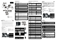
Product Profile & Outline
3
4
7
5
8
2
9
6
6
6
1
2
90 [3.543]
60 [2 .362]
6
3
.
4
[
2
.
4
9
6
]
33 .1 [1.303 ]
3 [0. 118 ]
IN 0
SHL D
GND
CAN-
DVPC OPM
ERR
NO
D
E
A
D
D
R
E
S
S
0
DR 2
DR 1
DR 0
x16
x16
1
POW ER
RUN
Unit: mm [inch]
1
Model name
2
Connection port for extension unit
3
Power, Run, Error indicators
4
DIN rail clip
5
Digital display
6
Fixing clip for extension unit
7
Address setup rotary switch
8
Function setup DIP switch
9
CANopen connector
ENGLISH
Specifications
CANopen Connector
Type Removable connector (5.08mm)
Transmission
method
CAN
Transmission cable 2 communication cables, 1 shielded cable and 1 grounding cable
Electrical isolation 500VDC
Communication
Message type PDO, SDO, SYNC (synchronous object), Emergency (emergency object), NMT
Series transmission
speed
10k, 20k, 50k,125k, 250k, 500k, 800k, 1M bps (bits per second)
Product code 64
Equipment type 0 (Non-Profile)
Company ID 477 (Delta Electronics, Inc.)
Electrical Specifications
Power voltage 24VDC (-15% ~ 20%) (supplied by the internal bus from MPU)
Power consumption
1.7W
Isolation voltage 500V
Weight (approx. g) 66 (g)
Environment
Interference
immunity
ESD (IEC 61131-2, IEC 61000-4-2): 8KV Air Discharge, 4KV Contact
Discharge
EFT (IEC 61131-2, IEC 61000-4-4): Power Line: 2KV, Digital I/O: 1KV
Analog & Communication I/O: 1KV
Damped-Oscillatory Wave: Power Line: 1KV, Digital I/O: 1KV
RS (IEC 61131-2, IEC 61000-4-3): 80MHz ~ 1000MHz , 1.4GHz ~ 2.0GHz ,
10V/m
Operation/Storage
Operation: 0ºC ~ 55ºC (temperature), 50 ~ 95% (humidity), pollution degree 2
Storage: -25ºC ~ 70ºC (temperature), 5 ~ 95% (humidity)
Shock/vibration
immunity
International standards: IEC 61131-2, IEC 68-2-6 (TEST Fc)/IEC 61131-2 &
IEC 68-2-27 (TEST Ea)
Certificates IEC 61131-2, UL508
Configuration
DVPCOPM-SL modules are numbered automatically from 1 ~ 8 according to
their distance from the MPU (1 is the closest one). Maximum 8 modules are
extendable
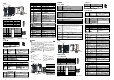
Installation
Connecting DVPCOPM-SL with SV series MPU
DVP28 SV
GN D
SH L D
CA N -
NODEADDRESS
DR 1
IN 0
DR 0
DR 2
x16
0
x16
1
ERR
RUN
POWER
DVP COPM
Components
CANopen Connector
PIN Signal Description
1 GND GND
2 CAN_L Signal-
3 SHLD Shielded cable
4 CAN_H Signal+
5 - Reserved
4
GND
SHLD
CAN-
CAN+
5
3
2
1
Function Setup DIP Switch
DR2 DR1 DR0 IN0 Baud Rate
OFF OFF OFF 10kbps
OFF OFF ON 20kbps
OFF ON OFF 50kbps
OFF ON ON 125kbps
ON OFF OFF 250kbps
ON OFF ON 500kbps
ON ON OFF 800kbps
ON ON ON
Reserved
1Mbps
DR 1
IN 0
DR 0
DR 2
Note: The setup of address and function is only valid when the power of DVPCOPM-SL is switched off.
Re-power the module after the setup is completed.
Address Setup Rotary Switch
Address Setting Description
1 ~ 7F Valid CANopen node address
0, 80 ~ FF Invalid CANopen node address
N
O
D
E
A
D
D
R
E
S
S
x16
0
x16
1
LED Indicator & Trouble-shooting
POWER LED
LED Status Indication How to deal with it
On Power is abnormal
1. Check if the PLC MPU is connected
normally to DVPCOPM-SL.
2. Check if the power supply for PLC
MPU is working normally.
Green light On Power is normal --
RUN LED
LED Status Indication How to deal with it
Off No power
Check the power of DVPCOPM-SL
and make sure the connection is
normal
Green light single flash
DVPCOPM-SL in STOP status
Green light blinking
DVPCOPM-SL in pre-operational
status
Green light steady on
DVPCOPM-SL in operational
status
--
ERROR LED
LED Status Indication How to deal with it
Off Normal No action needed
Red light single flash
Bus error exceeds the warning
limit
Check if the network connection and
operation are normal
Red light double flash Error control event
Check if the connection of
communication cable is normal.
Red light steady on Bus-off
Make sure the connection of
communication cable is normal and all
the nodes on the network share the
same communication speed, then
re-power DVPCOPM-SL.
Codes in Digital Display
Codes on digital display when DVPCOPM-SL is in master mode:
Code Indication How to deal with it
1 ~ 7F
The node address of DVPCOPM-SL
when in normal operation.
No action needed
F1 No slaves configured in node list
Re-configured the node list and download it to
DVPCOPM-SL
F2
The data are being downloaded to
DVPCOPM-SL
No action needed
F3 DVPCOPM-SL in error status Re-download the parameter configuration
Code Indication How to deal with it
F4 Bus-off is detected
Make sure the communication cable is in normal
operation and all the nodes in the network work
in the same baud rate. Re-power
DVPCOPM-SL.
F5 Wrong node address for DVPCOPM-SL
Set the node address of DVPCOPM-SL to be
between 1 ~ 127.
F6 ~ F8
Internal (device, GPIO check, memory)
abnormality is detected.
Re-power DVPCOPM-SL. If the error still exists,
change to a new DVPCOPM-SL
F9 Low voltage is detected.
Check and make sure the power of
DVPCOPM-SL works normally.
E0
DVPCOPM-SL receives Emergency
message sent by the Slave.
Read relevant information through PLC MPU.
E1
PDO data length returning from the
Slave is not consistent with the length
set in the Slave address
Reset the PDO data length in the Slave and
download the new setting to DVPCOPM-SL
E2
PDO message from the Slave has not
been received.
Check and make sure the setting is correct.
E3 Auto SDO download failed. Check and make sure Auto SDO is correct.
E4 PDO parameter setting has failed. Make sure the PDO parameter setting is legal.
E5 Error in key parameter setting
Make sure all the Slaves connected are
consistent with the Slaves set.
E6 The Slave does not exist in the network
E7 Slave’s Error control is time-out
Check if the connection of communication cable
and the power supply for slave are normal.
E8 Master/slave node address is repeated
Reset the node address and make sure the new
node address is not repeated one.
Codes on digital display when DVPCOPM-SL is in slave mode:
Code Indication How to deal with it
1~ 7F
The node address of DVPCOPM-SL
when in normal operation.
--
A0
The parameters in DVPCOPM-SL are
being initialized.
--
A1
DVPCOPM-SL is in pre-operational
status.
--
A3
The data are being downloaded to
DVPCOPM-SL.
--
B0 Heartbeat timed-out Re-connect DVPCOPM-SL to the network.
B1
PDO data length returned from the slave
is not consistent with the length set in
the node list.
Reset the PDO data length in the slave and
download the new setting to DVPCOPM-SL.
F4 Bus-off status detected
Make sure the communication cable is in normal
operation, and all the nodes on the network work
in the same baud rate. Re-power
DVPCOPM-SL.
FB
The sending buffer in DVPCOPM-SL is
full.
Make sure the bus works normally and re-power
DVPCOPM-SL.
FC
The receiving buffer in DVPCOPM-SL is
full.
Make sure the bus works normally and re-power
DVPCOPM-SL.
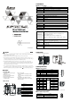
DVPCOPM-SL CANopen
CANopen
Open Type
/
/
1. CANopen DS301v4.02
2. NMT
3. Error Control Protocol
4. SDO
5. CANopen EDS
6. PDO
RxPDO 200 390
TxPDO 200 390
7. PDO
3
4
7
5
8
2
9
6
6
6
1
2
90 [3.543]
60 [ 2.362]
6
3
.
4
[
2
.
4
9
6
]
33 .1 [1.303 ]
3 [0 .118]
IN 0
SHL D
GND
CAN-
DVPC OPM
ERR
N
O
D
E
A
D
D
R
E
S
S
0
DR 2
DR 1
DR 0
x16
x16
1
POW ER
RUN
mm [inch]
1
2
3
Power Run Error
4
DIN
5
6
7
8
9
CANopen
CANopen
(5.08mm)
CAN
500VDC
PDO SDO SYNC Emergency NMT
10k 20k 50k 125k 250k 500k 800k 1M bps /
64
0 Non-Profile
ID 477
24VDC (-15% ~ 20%)
1.7W
500V
( ,g)
66 (g)
ESD (IEC 61131-2, IEC 61000-4-2): 8KV Air Discharge, 4KV Contact Discharge
EFT (IEC 61131-2, IEC 61000-4-4): Power Line: 2KV, Digital I/O: 1KV
Analog & Communication I/O: 1KV
Damped-Oscillatory Wave: Power Line: 1KV, Digital I/O: 1KV
RS (IEC 61131-2, IEC 61000-4-3): 80MHz ~ 1000MHz , 1.4GHz ~ 2.0GHz , 10V/m
/
0ºC ~ 55ºC 50 ~ 95% 2
-25ºC ~ 70ºC 5 ~ 95%
/
IEC 61131-2 IEC 68-2-6 (TEST Fc)/IEC 61131-2 & IEC 68-2-27
(TEST Ea)
IEC 61131-2 UL508
DVPCOPM-SL 1 ~ 8 8