DF CE -NNN 4 0 -DT xR DFCE-NNN40-DTXR mbed Kit User Guide mbed Kit User Guide Sheet 1 of 15 Proprietary Information and Specifications are Subject to Change Aug 11, 2015
DF CE -NNN 4 0 -DT xR Index: 1. Introduction................................................................................................................ 4 1.1 Minimum Requirements ..................................................................................................... 4 2. Kit Content ................................................................................................................. 4 2.1 DELTA DFCE-NNN40 mbed kit hardware content ...........................................
DF CE -NNN 4 0 -DT xR Revision History Version Date 0.1 2015/2/11 Reason of change First release Maker Tsungta Wu a. Remove Virtual COM port feature from HDK in whole document b. update section 1, section 1.1, section 2.1, section 4, section 4.1 to improve readability c. add section 2.2 DELTA DFCE-NNN40 mbed kit hardware figure d. change 3.3V to 3.6V and 3V3 to 3V6 in whole 0.2 2015/4/14 document Tsungta Wu e. Change document title and footnote f. Remove UV sensor in the whole g.
DF CE -NNN 4 0 -DT xR Wireless LAN/Bluetooth Low Energy Combo Module MBED Kit Getting Start 1. Introduction The DELTA DFCE-NNN40 development kit provides cost effective, low power, and flexible platform to rapid prototype of Wi-Fi® connectivity and Bluetooth Low Energy design. Kit has temperature sensor on board, it is convenient to set up example application and develop the relative prototype. The core of DELTA DFCE-NNN40 is DFCE-NNN40-DTxR module embed nRF51822 BLE SoC which integrating the 2.
DF CE -NNN 4 0 -DT xR 2.
DF CE -NNN 4 0 -DT xR 2.3 Downloadable Content 2.3.1 nRF51822 documentation • nRF51 Series Reference Manual • nRF51822 Product Specification • S110 nRF51822 SoftDevice Specification • nRF51822 Product Anomaly Notification All documents can be found from the link below http://www.nordicsemi.com/eng/Products/Bluetooth-Smart-Bluetooth-low-energy 2.3.2 Hardware related files • Schematics • Placement All documents can be found from DELTA DFCE-NNN40 platform page https://developer.mbed.
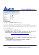
DF CE -NNN 4 0 -DT xR Windows Example 3.2 Click the MBED.HTM file to log in (1) Go to the new USB Drive and click MBED.HTM to open it in a web browser. (2) If you do not have an mbed account, click Signup to create your mbed account. Otherwise, log in with your normal username and password. This will give you access to the website, tools, libraries, and documentation. 3.3 Setup Virtual Com Port Driver DELTA DFCE-NNN40 support CDC device. At step 3.1, the PC may have an unrecognized device.
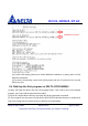
DF CE -NNN 4 0 -DT xR (3) Double click dpinst_ia64.exe for 64-bit Windows installation or dpinst_x86 for 32-bit Windows installation. (4) To test the functionality, connect the (CN3) jumper and use PC terminal tool to test the UART loop test. 3.4 Build up the first program on DELTA DFCE-NNN40 (1) After you login the mbed, click the new program button. Then choice one of the example program, the project will be generated from mbed.
DF CE -NNN 4 0 -DT xR (4) During the image uploading, the (LD8) should blink to indicate the uploading state. (5) When the uploading is completed, the succ.txt should be appeared in USB drive. Then the uploaded application starts running on DELTA DFCE-NNN40. 4. Kit Description. 4.
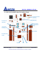
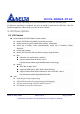
DF CE -NNN 4 0 -DT xR 4.2 Kit PIN OUT DELTA DFCE-NNN40 has a default profile pin out. The board has reserved SPI, I2C, ADC, UART and GPIO pin to access. The following is the detail of description for pin out. 1.8V pin The voltage of power supply for BLE module is 1.8V. All BT GPIO (P4~P29), are connected to BLE SoC. It is notice that the voltage should be 1.8V. 3.6V pin There are pins are passed through level shift to convert from 1.8V to 3.6V. Those are SCL_3V6, SDA_3V6, STLK_TX, and STLK_RX.
DF CE -NNN 4 0 -DT xR mbed Kit User Guide Sheet 11 of 15 Proprietary Information and Specifications are Subject to Change Aug 11, 2015
DF CE -NNN 4 0 -DT xR 4.3 HDK Reset The Reset button (SWDIO) is connected to the embedded Nordic nRF51822; it is working no matter the power supply is from USB or external power. 4.4 Power Supply USB External power supply from VIN (5V) To select power supply, the JP5 is used to switch power source.
DF CE -NNN 4 0 -DT xR 4.5 Button and LED The two user buttons and two LEDs on the mbed kit board are connected to dedicate I/Os on the nRF51822 chip. The connections are shown in blew table. Part GPIO Short Button0 P16 Button1 P17 LED0 (LD7) P07 R132 LED1 (LD6) P13 R123 4.6 UART Configuration Below table shows an overview of the UART connections on DELTA DFCM-NNN40, refer to section 3.
DF CE -NNN 4 0 -DT xR 4.7 Measuring Current The current drawn by the DFCE-NNN40-DTxR module can be monitored on the DELTA DFCEM-NNN40 mbed kit. To measure the current, you must first prepare the board by removing the 0Ω on R127and R128. To measure the current of BLE chip, please connect current meter series to 1V8 and BLE_1V8_IN pin on CN7; while the current of Wi-Fi chip measurement, please connect current meter series to 3V6 and WIFI_3V6_IN pin on CN7. 5.
DF CE -NNN 4 0 -DT xR -Reorient or relocate the receiving antenna. -Increase the separation between the equipment and receiver. -Connect the equipment into an outlet on a circuit different from that to which the receiver is connected. -Consult the dealer or an experienced radio/TV technician for help. This device complies with Part 15 of the FCC Rules.