DVPEN01-SL Ethernet Communication Module Application Manual
Ethernet Communication Module DVPEN01-SL Warning 3 Please read this instruction carefully before use and follow this instruction to operate the device in order to prevent damages on the device or injuries to staff. 3 Switch off the power before wiring. 3 RTU-DNET is an OPEN TYPE device and therefore should be installed in an enclosure free of airborne dust, humidity, electric shock and vibration. The enclosure should prevent non-maintenance staff from operating the device (e.g.
Ethernet Communication Module DVPEN01-SL 5.6 IP Filter ..................................................................................................................................... 23 5.7 Static ARP Table ....................................................................................................................... 24 5.8 Setting up Password................................................................................................................. 25 5.
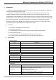
Ethernet Communication Module DVPEN01-SL 1 Introduction Thank you for choosing DVPEN01-SL module. To correctly install and operate DVPEN01-SL, please read the manual carefully before using the module. DVPEN01-SL is an Ethernet communication module for remote setting and communication through WPLSoft. DVPEN01-SL is able to send E-mails, automatically correct the RTC in DVP28SV11R/T and exchange data.
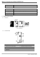
Ethernet Communication Module DVPEN01-SL Item Vibration/ Shock Resistance Specification Standard: IEC61131-2, IEC 68-2-6 (TEST Fc)/IEC61131-2 & IEC 68-2-27 (TEST Ea) Electrical specifications Item 2 Specification Power supply voltage 24VDC (-15% ~ 20%) (Power is supplied by the internal bus of MPU.) Power consumption 1.5W Insulation voltage 500V Weight (g) 92 (g) Product Profile & Outline 2.1 Dimension 3 [0.118] DVPEN01 POWER RS-232 100M 90 [3.543] LINK RS-232 60 [2.
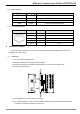
Ethernet Communication Module DVPEN01-SL 2.3 2.4 LED Indicators Indicator Color Indication POWER Green Power indication RS-232 Red Communication status of the series port 100M Orange Network connection status LINK Green Network communication speed RJ-45 PIN Definition RJ-45 sketch 3 Terminal No.
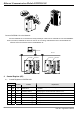
Ethernet Communication Module DVPEN01-SL Connect DVPEN01-SL to the Network Connect DVPEN01-SL to the Ethernet Hub by twisted pair cable CAT-5e. DVPEN01-SL has Auto MDI/MDIX function; therefore, DVPEN01-SL does not need to use a crossing cable between the PC and DVPEN01-SL. Network connection between the PC and DVPEN01-SL: PC Master Ethernet DVPEN01 DVPEN01 DVP28SV DVP28SV RS-232 RS-232 100M 100M DVP28SV LINK LINK RS-232 RS-232 LAN LAN Control Register (CR) 4.
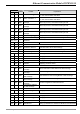
Ethernet Communication Module DVPEN01-SL CR# HW LW Attribute Content Status of E-Mail 1, 2 Explanation b0 ~ b7: Current status of E-Mail 2 b8 ~ b15: Current status of E-Mail 1 b0 ~ b7: Current status of E-Mail 4 b8 ~ b15: Current status of E-Mail 3 #7 R #8 R #9 R/W #10 R/W #11 R/W #12 R/W #13 R/W #14 R Status of data exchange Displaying current status of data exchange.
Ethernet Communication Module DVPEN01-SL CR# HW Attribute LW Content Explanation #119 R/W Modbus TCP data length Setting up the data length for Modbus TCP transaction #219 ~ #120 R/W Modbus TCP data buffer Data buffer of Modbus TCP for storing sending/receiving data #248 ~ #220 - Reserved #251 R Error code #255 ~ #252 - Reserved Displaying the errors. See table of error codes in the following section for more information.
Ethernet Communication Module DVPEN01-SL CR value E-Mail status 10 Fail to connect to SMTP-Server 11 Incorrect recipient E-Mail address 12 SMTP-Server communication error 13 Exceeding the max. number of TCP connection 3 ~ 9, 14 ~ 255 Reserved C R # 9 ~ 12: E-Mail 1 ~ 4 Additional Message Explanations: The user fills in the code, and the code will be stored in the title of the E-Mail and sent out with the E-Mail.
Ethernet Communication Module DVPEN01-SL Storing the data to be transmitted to the remote MPU. CR# 49 ~ 68 : Data Receiving Buffer Explanations: Storing the data received from the remote MPU. CR#81: Read Address for Data Exchange Explanations: Setting up manually the Modbus address of the register for Slave data exchange. Only register address is allowed (e.g. D0 = H’1000). CR#82: Read Length for Data Exchange Explanations: The number of receiving registers (K1 ~ K128) in data exchange.
Ethernet Communication Module DVPEN01-SL CR#70, 71: IP Address Explanations: 1. Setting up the IP address of our equipment in hex. When in DHCP mode, you can only read and cannot write. 2. Example: Assume you’d like to set the IP address as 192.168.0.2, you have to write H’0002 into CR#70 and H’C0A8 into CR#71 to complete the setting. (K192 = H’C0, K168 = H’A8, K0 = H’00, K2 = H’02) CR#72, 73: Subnet Mask Explanations: 1. Setting up the subnet mask of our equipment in hex.
Ethernet Communication Module DVPEN01-SL CR#116: Modbus TCP Status Explanations: Displaying the current communication status of Modbus TCP mode. When the CR value is set as”0” Æ the data have not yet been received; when the CR value is set as “1” Æ the data exchange is in progress; when the CR value is set as “2” Æ the data exchange is successful; when the CR value is set as “3” Æ the data exchange fails. CR value Data exchange status 0 The data have not been received.
Ethernet Communication Module DVPEN01-SL registers (CR) in the extension module. Numbering of the modules: Every extension module connected to PLC MPU has a No. to allow you to know which module is which when compiling the PLC program. The first extension module attached at the left hand side of the PLC MPU is numbered as K100, the second as K101, the third K102, and so on. 5 Setting up Software This section gives instructions on how to set up DVPEN01-SL by WPLSoft and explanations on each setup page.
Ethernet Communication Module DVPEN01-SL 2. Auto-search • Press “Auto-Search” (circled) to search for every DVPEN01-SL in the network and display them in the left column. • Move the cursor to the module you would like to set up. Double click it to enter the setup page. • You will see the basic setup page as follow.
Ethernet Communication Module DVPEN01-SL 3. Searching by IP address • Set the transmission type as “Ethernet” first. Next click on the “Static IP Search” icon (circled) to search for the designated IP. • Press the “search” icon and you will open the window for entering the IP address. Enter the IP of DVPEN01-SL you would like to search in the IP address column, or click on the IP address in the IP list. Press “OK" to start the searching. • The DVPEN01-SL searched is displayed in the left column.
Ethernet Communication Module DVPEN01-SL 4. Opening DVPEN01-SL setup page by RS-232` • Select “RS232" as the transmission type in communication setting. You will have to designate a communication port. When DVPEN01-SL is searched by RS-232, you do not need to set up the parameters (i.e. data length, parity, stop bits and baud rate). • After setting up the communication port, press “RS-232 search” icon (circled). If the searching is successful, the setup page for DVPEN01-SL will open automatically. 5.
Ethernet Communication Module DVPEN01-SL • Module Name: There can be many DVPEN01-SL modules in the network. Thus, you can set up a module name for each module to identify the module when you need to use them. • Module Language: You can select a language for each module name, and the windows will be displayed in the selected language. • Enable Modbus TCP: To enable or disable Modbus TCP. When Modbus TCP is disabled, WPLSoft will not be able to upload or download.
Ethernet Communication Module DVPEN01-SL sections), bordered by meridians each 15° of longitude apart. The local time in neighboring zones is then exactly one hour different. However, political and geographical practicalities can result in irregularly shaped zones that follow political boundaries or that change their time seasonally (as with daylight saving time), as well as being subject to occasional redefinition as political conditions change. You should choice the Time zone that you are. 5.
Ethernet Communication Module DVPEN01-SL • Enter 192.168.0.1 into IP address. Click on “OK” to complete the IP address setting of the PC. 2. Setting up DVPEN01-SL Network • IP configuration: There are two types of IP, static IP and DHCP. Static IP: Preset or manually modified by the user. DHCP: Automatically updated by the server. There has to be a server in the LAN.
Ethernet Communication Module DVPEN01-SL IP Explanation Static The user enters the IP address, subnet mask and gateway. DHCP DHCP server offers the IP address, subnet mask and gateway. • IP address: IP address is the location of the equipment in the network. Every equipment connected to the network has to have an IP address. Incorrect IP address will result in connection failure on the equipment or even other equipment. Ask your ISP for questions about IP address setup.
Ethernet Communication Module DVPEN01-SL 1. SMTP Server: The E-Mail will first be sent to SMTP server, and SMTP server will send it to the designated address. For example, assume there is an E-Mail to be sent to test@delta.com.tw, and the SMTP server is 172.16.144.121. The E-Mail will be sent to SMTP server first, and the server will further send it to the recipient test@delta.com.tw. 2.
Ethernet Communication Module DVPEN01-SL 5. Select recipients: After you have set up all the parameters for the E-Mail, you will need to select recipients. The E-Mail will be sent to the designated recipients when the E-Mail is triggered. To trigger E-Mail, set the value is CR#3 ~ CR#6 as “1”. 6. See “Application Examples Section 6.8” for more details. Notes: To correctly send out E-Mails, there has to be a SMTP server in the network.
Ethernet Communication Module DVPEN01-SL 1. Enable Data Exchange: Check the box to enable or disable data exchange. Start data exchange after enable it. 2. Communication Address & Data exchange host IP: You have to enter the IP address of DVPEN01-SL at the other end. For example, if you would like DVPEN01-SL to exchange data with 192.168.0.1, set No. 1 as 192.168.0.1. When the data are being exchanged, if the value in CR#28 is H’0001, the data will be exchanged with 192.168.0.1. 3.
Ethernet Communication Module DVPEN01-SL 1. Enable IP Filter Function: Check the box to enable IP filter. 2. IP: IP addresses that are allowed to establish connections. Maximum 8 IPs are allowed. 3. Netmask: The subnet of the IP is allowed to establish a connection. To see whether the destination IP is allowed, conduct bitwise AND operations between the allowed IP and subnet mask and destination IP and subnet mask. If the two values obtained are the same, the destination IP is allowed by the IP filter.
Ethernet Communication Module DVPEN01-SL 1. IP: Destination IP address in data transmission. 2. MAC: The MAC address corresponding to the IP address. Note: Incorrect settings may result in connection failure. Therefore, DO NOT set the MAC address of the equipment without the network into the table. 5.8 Setting up Password To prevent the set values in DVPEN01-SL from being modified, you can set up password to lock the settings in DVPEN01-SL.
Ethernet Communication Module DVPEN01-SL 1. Modify: Check the box to modify the password. 2. New Password: Maximum 4 characters are allowed. Leave the column “blank” to disable the password protection function. 3. Confirm Password: Enter the new password again. 4. See “Application Examples Section 6.4” for more details. Note: After the password is locked, all the pages cannot be set up unless you unlock the password.
Ethernet Communication Module DVPEN01-SL Check “Default Setting” box and click on “Yes”. Note: If you set up DVPEN01-SL by RS-232, you can return the setting to default setting whether the password is locked or not. It takes approximately 10 seconds to return to default setting, so DO NOT switch off the power within the 10 seconds. 5.10 Export & Import of DVPEN01-SL Files After you set up all the settings in DVPEN01-SL, you can export you settings and save them into files.
Ethernet Communication Module DVPEN01-SL 1. Export: Save all the settings of DVPEN01-SL into *.eni files. The exported files do not include the password. 2. Import: Select a file and the file will be imported to all the settings. 5.11 Recording IP Address When DVPEN01-SL is searching for a designated IP, there is a list for you to directly select and designate a module to be searched. “Recording IP address” function is to add a DVPEN01-SL module into the list for you to see the module in the searching.
Ethernet Communication Module DVPEN01-SL Input IP Address: Press “Add” to record the IP address of the module into the list. 6 Application Examples 6.1 Setting up IP and Communicating through WPLSoft Application Setting up network parameters of DVPEN01-SL directly on the PC. Network requirement (1) IP of PC executing WPLSoft: 192.168.0.3 (2) Subnet mask: 255.255.255.0; Gateway: 192.168.0.1 (3) IP of DVPEN01-SL: 192.168.0.4 (4) Connect the PC and DVPEN01-SL by RJ-45 cable.
Ethernet Communication Module DVPEN01-SL 4. Click on “Auto-Search” icon to search for all DVPEN01-SL modules in the network. 5. Designate a DVPEN01-SL and double click it to open the setup page.
Ethernet Communication Module DVPEN01-SL 6. Open “Basic” setup page. 7.
Ethernet Communication Module DVPEN01-SL 8. Enter IP address: 192.168.0.4; Netmask: 255.255.255.0; Gateway: 192.168.0.1. Press “OK” to complete the setup, and WPLSoft will automatically search for DVPEN01-SL. 9. The IP of DVPEN01-SL has been modified into the new setting (DELTA DVPEN01-SL: 192.168.0.4). 10. Click on DELTA DVPEN01-SL, and WPLSoft will be able to communicate with the MPU. 6.
Ethernet Communication Module DVPEN01-SL DHCP Server PC DVPEN01 DVP-PLC PC Hub 2. Open “Communication Setting” in WPLSoft. 3. Select “Ethernet” and press “OK”.
Ethernet Communication Module DVPEN01-SL 4. Click on “Auto-Search” icon to search for all DVPEN01-SL modules in the network. Follow “View Æ Workspace Æ Communication” or “View Æ Workspace Æ Project” to find the detected DVPEN01-SL module (default module name: DELTA DVPEN01-SL, IP: 192.168.1.5) in the window. 5. Designate a DVPEN01-SL and double click it to open the setup page.
Ethernet Communication Module DVPEN01-SL 6. Open the setup page. You can modify the module name for easier identification. 7. Next, set up the new IP of DVPEN01-SL. First switch to “Network” setup page. If there is a DHCP server in the LAN, select DHCP in “IP Configuration”. If there is no DHCP server in the LAN, you can set a static IP. Please be noted that the settings of subnet mask and gateway have to be the same as the settings in the same LAN.
Ethernet Communication Module DVPEN01-SL 6.3 Setting up IP and Communicating through WPLSoft Application Setting up network parameters of DVPEN01-SL by ladder diagram Network requirement (1) IP of DVPEN01-SL: 192.168.0.4 (2) Subnet mask: 255.255.255.0; Gateway: 192.168.0.1 (3) If DVPEN01-SL is damaged, change to a new DVPEN01-SL and execute STOP→RUN. The IP of the new DVPEN01-SL will be modified into 192.168.0.4. (4) DVPEN01-SL is the first extension module attached in the left hand side of PLC. 1.
Ethernet Communication Module DVPEN01-SL • Use TO instruction to write the network setting parameters D0 ~ D7 into CR#69 ~ #75 in DVPEN01-SL. DVPEN01-SL is the first extension module numbered K100 attached at the left hand side of PLC. (See 4.3 for more details.) • After the program is being executed, all the previous network settings in DVPEN01-SL will be modified into new settings. 3. If DVPEN01-SL is damaged, please change to a new DVPEN01-SL. The default IP for DVPEN01-SL is 192.168.1.5. 4.
Ethernet Communication Module DVPEN01-SL 4. Open the setup page again, and DVPEN01-SL is now locked by the password. You cannot open any of the settings now. Click on “Unlock” to leave the entering password window. 5. Enter the password to temporarily unlock the protection and modify the parameters. If you close the setup page, the locking will automatically be recovered.
Ethernet Communication Module DVPEN01-SL 6. To clear the password, simply leave the password columns blank. Click on “OK” to clear the password. 7. After the password is cleared, you can modify the parameters. 6.5 When the Password is Lost (Returning to Default Setting by RS-232) Application Returning to default setting by RS-232 Network requirement (1) DVPEN01-SL is set with a password. (2) The password is forgotten. 1. Use DVPACAB2A30 cable to connect the PC and DVPEN01-SL and open the setup page.
Ethernet Communication Module DVPEN01-SL 2. Check the “Default Setting” box and the “Warning” dialog box will appear. Click on “Yes” to return to default setting (in approx. 5 ~ 10 seconds), and the password will be cleared as well. 3. After the searching, all the parameters have already returned to their default settings. 6.6 IP Filter Protection Application Setting up IP filter protection Network requirement (1) IP of DVPEN01-SL: 192.168.0.4 (2) Only connections to 192.168.0.7 and 172.16.0.1~172.
Ethernet Communication Module DVPEN01-SL 3. Check “Enable IP Filter Function” box. Enter “192.168.0.7” in No. 1 IP and “255.255.255.255” in all “Netmask” columns. 4. Enter “192.168.0.1” in No. 2 IP and “255.255.255.0” in No.2 “Netmask” column. Click on "OK” to complete the setting. Only the equipment within the IP range can be connected.
Ethernet Communication Module DVPEN01-SL 6.7 Setting up Static ARP Table Application Setting up static ARP table Network requirement (1) MAC address of equipment 192.168.1.6 is 00:18:23:10:00:35 (2) MAC address of equipment 192.168.1.1 is 00:18:23:10:00:04 1. See 6.1 for the connection and how to set up the communication. 2. Open the setup page and switch to “Static ARP Table” page. 3. Check “Enable ARP Table” box. Enter “192.168.1.6” in No.
Ethernet Communication Module DVPEN01-SL Note: The MAC address of DVPEN01-SL can be obtained from WPLSoft or the MAC address sticker on the equipment. The MAC address of PC can be found in the “Network Connection Details” (see below). 6.8 Application of E-Mail Application Network application Sending an E-Mail to notify the administrator when the current status of X0 and Y0 is changed. (1) SMTP Server IP: 172.16.144.121。 (2) E-mail address of administrator: test@sample.
Ethernet Communication Module DVPEN01-SL 3. In “Subject and Mail” page, enter the address of SMTP server, subject of E-Mail, and E-mail address of the recipient. 4. Switch to “Select Recipients” page. Check all the boxes of “Recipient 1”. Click on “OK” to complete the setting.
Ethernet Communication Module DVPEN01-SL 5. After all the settings in DVPEN01-SL are completed, compile the ladder diagram in the MPU and download it to the MPU. See below for the program design: X0 T0 K100 K3 K1 K1 T0 K100 K4 K1 K1 T0 K100 K5 K1 K1 T0 K100 K6 K1 K1 X0 Y0 Y0 END Explanations: • If the rising-edge of X0 is triggered, X0 will go from Off to On. Write “1” into CR#3 of DVPEN01-SL, and the first E-Mail will be sent out.
Ethernet Communication Module DVPEN01-SL 3. Check “Enable Data Exchange” box. Enter IP address of PLC_A “192.168.0.4” in No. 1 Data Exchange Host IP column. Click on “OK” to complete the setting. 4. After all the settings in PLC_B are completed, compile the ladder diagram in the MPU and download it to PLC_B.
Ethernet Communication Module DVPEN01-SL • Write the data in RTC into CR#29 ~ CR#35. • Write “1” into CR#13 to start the data exchange. • CR#14 = 2 refers to successful exchange. CR#14 = 3 refers to failed exchange. 5. Compile the ladder diagram for PLC_A and download it to PLC_A. M1013 FROM K100 K49 D0 K7 END Explanations: • The received data are stored in CR#49 ~ CR#55. • The data received every one second are written into D0 ~ D6. 6.
Ethernet Communication Module DVPEN01-SL Explanations: • The data exchange will be executed every one second. • Write “0” into CR#28, and PLC_B will use CR#25 ~ CR#26 as the IP address of the destination PLC. • Write the IP address of PLC_A into CR#25 and CR#26. The first two IP codes (192.168 = H’C0A8) should be written into CR#26, and the last two IP codes (0.4 = H’0004) into CR#25. • Write the data in RTC into CR#29 ~ CR#35. • Write “1” into CR#13 to start the data exchange.
Ethernet Communication Module DVPEN01-SL TOP K100 K86 H1064 K1 TOP K100 K14 K0 K1 TOP K100 K13 K1 K1 SET M2 RST M1 FROM K100 K14 D14 K1 = D14 K2 RST M2 = D14 K3 RST M2 M2 END Explanations: • The data exchange will be executed every one second. • Write “0” into CR#28, and PLC_B will use CR#25 ~ CR#26 as the IP address of the destination PLC. • Write the IP address of PLC_A into CR#25 and CR#26. The first two IP codes (192.
Ethernet Communication Module DVPEN01-SL M1013 M2 M1 SET M1 TOP K100 K118 HC0A8 K1 TOP K100 K117 H4 K1 TOP K100 K111 K1 K1 TOP K100 K120 H0 K1 TOP K100 K121 H5 K1 TOP K100 K122 H5 K1 TOP K100 K123 H0 K1 = D0 K0 TOP K100 K124 HFF K1 = D0 K1 TOP K100 K124 H0 K1 TOP K100 K125 H0 K1 TOP K100 K119 K6 K1 TOP K100 K116 K0 K1 TOP K100 K115 K1 K1 INC D0 MOV K0 SET M2 RST M1 FROM K100 D14 K1 = D14 K2 RST M2 = D14 K3 RST M2 M1 =
Ethernet Communication Module DVPEN01-SL • Write the length of the instrcution into CR#119. • Write “1” into CR#115 to start the execution of Modbus TCP instrcution. • CR#116 = 2 refers to successful execution. CR#116 = 3 refers to failed execution. • If the execution is successful, Y0 on PLC_A will go between On and Off every one second.
Ethernet Communication Module DVPEN01-SL MEMO 52 DVP-PLC Application Manual