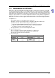
Training Kit Operation Manual Table of Contents Chapter 1 Introduction of PLCs 1.1 Introduction of DVP12SE.......................................................................... 1-2 1.2 Introduction of DVP20SX2........................................................................ 1-3 1.3 Introuction of DVP28SV2.......................................................................... 1-4 1.4 Introduction of DVP12SA2........................................................................ 1-5 1.5 1.6 1.
Chapter 4 Operating a Training Kit 4.1 Introduction of a Training Kit .....................................................................4-2 4.2 Functions of DVP12SE .............................................................................4-3 4.3 Functions of DVP28SV2 ...........................................................................4-9 4.4 Functions of DVP20SX2 .........................................................................4-20 4.5 Functions of DVP12SA2 ...........................
iii
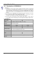
Chapter 1 Introduction of PLCs The functions of PLCs and the features of modules described in this chapter help users choose the proper models they need to perform some functions. Table of Contents 1.1 1.2 1.3 1.4 1.5 1.6 1.7 1.8 Introduction of DVP12SE.......................................................................... 1-2 Introduction of DVP20SX2........................................................................ 1-3 Introuction of DVP28SV2....................................................
Tr ain i n g K it O pe r a t io n Ma n ua l 1.1 Introduction of DVP12SE DVP-SE is a 12-point (8 DI+4 DO) PLC MPU, offering various instructions and with 16K steps program memory, able to connect to all DVP Slim type series extension modules and high-speed extension modules, including digital I/O (max. 480 I/O points) and analog modules (for A/D, D/A conversion and temperature measurement). 2 points of 100 kHz and 2 points of 10 kHz high-speed pulse output satisfy all kinds of applications.
Ch a pt er 1 In tr od uc t i o n of P L Cs 1.2 Introduction of DVP20SX2 DVP-SX2 is a 20-point (8 DI+6 DO+4 AI+2 AO) PLC MPU, offering various instructions and is with 16k steps program memory, able to connect with all Slim series extension models, including digital input/output (max. 480 input/output extension points), analog modules (A/D, D/A transformation and temperature units) and all kinds of new high-speed extension modules.
Tr ain i n g K it O pe r a t io n Ma n ua l 1.3 Introuction of DVP28SV2 DVP-28SV2 is a 28-point (16 inputs+12 outputs) PLC MPU, offering various instructions and with 30K (SV2) steps program memory, able to connect to all Slim type series extension models, including digital I/O (max. 512 points), analog modules (for A/D, D/A conversion and temperature measurement) and all kinds of high-speed extension modules. 1.
Ch a pt er 1 In tr od uc t i o n of P L Cs 1.4 Introduction of DVP12SA2 DVP-SA2 is a 12-point (8 DI+4 DO) PLC MPU, offering various instructions and with 16K steps program memory, able to connect to all DVP-S series extension modules and high-speed extension modules, including digital I/O (max. 480 I/O points) and analog modules (for A/D, D/A conversion and temperature measurement). 2 points of 100 kHz and 2 points of 10 kHz high-speed pulse output satisfy all kinds of applications.
Tr ain i n g K it O pe r a t io n Ma n ua l 1.5 Introduction of DVP06XA-S 1. Introduction DVP06XA-S is able to receive 4 points of analog input signals (voltage or current) and convert them into 12-bit digital signals. DVP06XA-S receives 2 groups of 12-bit digital data from the PLC MPU and converts them into 2 points of analog signals for output (in voltage/current).
Ch a pt er 1 In tr od uc t i o n of P L Cs Mixed analog/digital (A/D) module Voltage input Current input Mode 0: (-10 V~+10 V); Mode 1: (-6 V~+10 V) +20 00 Mode 0 Digital output Mode 1 +10 00 5V 0 - 10V 6V 2V -6V 10V OFFSET GAI N -1000 Conversion Curve (Default setting: Mode 0) Voltage input - 2000 Mode 2: (-12 mA~+20 mA); Mode 3: (-20 mA~+20 mA) Mode 3 +10 00 Digital output -20mA Mode 2 -12mA 0 4mA 20mA GAI N OFF SET - 1000 Mixed digital/analog (D/A) module Analog signal output
Tr ain i n g K it O pe r a t io n Ma n ua l Mixed digital/analog (D/A) module Communication mode (RS-485) Connect to DVP-PLC MPU in series Voltage output Current output MODBUS ASCII/RTU Mode. Communication baud rate of 4,800/9,600/19,200/38,400 /57,600/115,200. For ASCII mode, date format is 7 bits, even, 1 stop bit (7, E, 1). For RTU mode, date format is 8 bits, even, 1 stop bit (8, E, 1). The RS-485 is disabled when the DVP06XA-S is connected in series with MPU.
C h a pt er 1 In tr od uc t i o n of P L C s 1.6 Introdunction of DVP04PT-S 1. Introduction DVP04PT-S is able to receive 4 points of platinum temperature sensors and convert them into 16-bit digital signals. Besides, through FROM/TO instructions in DVP Slim series MPU program, the data in DVP04PT-S can be read and written. There are many 16-bit control registers (CR) in DVP04PT-S. The power unit is separate from it and is small in size and easy to install. 2.
Tr ain i n g K it O pe r a t io n Ma n ua l DVP04PT-S Temperature/Digital Value Characteristic Curve Celsius (°C) Mode of measuring Celsius temperature: Fahrenheit (°F) Mode of measuring Fahrenheit temperature: 3. Other specifications Maximum power consumption Operation/storage Vibration/shock immunity 1-10 Power supply 2 W at 24 V DC (20.4 V DC~28.
C h a pt er 1 In tr od uc t i o n of P L C s 1.7 Introduction of DVPEN01-SL 1. Introduction DVPEN01-SL is an Ethernet communication module for remote setting and communication through WPLSoft. DVPEN01-SL is able to send E-mails, automatically correct the RTC in a PLC and exchange data. It supports Modbus TCP communication protocol and can conduct remote monitoring by using SCADA (Supervisor Control and Data Acquisition) software or HMI (Human Machine Interfaces).
Tr ain i n g K it O pe r a t io n Ma n ua l Item 1-12 Specifications Insulation voltage 500 V Weight (g) 92 (g)
C h a pt er 1 In tr od uc t i o n of P L C s 1.8 Introduction of DVPCOPM-SL 1. Introduction DVPCOPM-SL can be used as the master in CANopen network, as well as the slave for other masters. As a master, DVPCOPM-SL features: Complying with CANopen standard protocol DS301v4.02 Supporting NMT Master Service Error control: Supporting Heartbeat/Node Guarding Protocol Supporting PDO Service Max. 200 RxPDOs and 390 bytes of data Max.
Tr ain i n g K it O pe r a t io n Ma n ua l Supporting Emergency Protocol Able to indicate Emergency event in slave through digital display 2. Sepcifications CANopen connection Item Specifications Transmission method CAN Electrical isolation 500 V DC Interface Removable connector (5.
Chapter 2 Setting an HMI Delta DOP-BN series human machine interfaces are introduced in this chapter. Users can create new projects and set functions by means of DOPSoft. Please refer to DOPSoft User Manual for more information. Table of Contents 2.1 Introduction of DOP-B07E515 .................................................................. 2-2 2.1.1 Hardware Specifications.................................................................... 2-2 2.1.2 Part Names ........................................
Tr ain i n g K it O pe r a t io n Ma n ua l 2.1 Introduction of DOP-B07E515 2.1.
Ch a pt er 2 S e tt i ng a n HM I Model B07E515 Panel cutout 172.4x132.4 (W)x(H)mm Weight Approx. 800 g Note1: The half-life of backlight is defined as original luminance being reduced by 50% when the maximum driving current is supplied to HMI. The life of LED backlight shown here is an estimated value under 25oC normal temperature and humidity conditions. Note2: USB Host port can provide up to 5 V/500 mA of power. Note3: The withstand voltage of the isolated power circuit is 1500 V peak for 1 minute.
Tr ain i n g K it O pe r a t io n Ma n ua l Rear view A F Power input terminal USB Slave COM2 (can be extended to B G System key COM3) (Note) C H COM1 Ethernet interface (LAN) Memory card slot/Battery D I Audio output interface cover E USB Host Note: For the setting method, please refer to the pin definition of serial communication. 2.1.
Ch a pt er 2 S e tt i ng a n HM I COM1 port (Supports flow control) COM port PIN1 Pin 1 2 3 4 5 6 7 8 9 Contact RS-232 RXD TXD GND RTS CTS Note: Blank=No connection COM2 and COM3 port COM port PIN1 Pin 1 2 3 4 5 6 7 8 9 MODE 1 MODE 2 MODE 3 COM2 COM3 COM2 COM3 COM2 COM3 RS-232 RS-485 RS-485 RS-485 RS-232 RS-422 D+ TXD+ RXD RXD TXD TXD D+ D+ RXD+ GND GND GND DTXD- DDNote 1: Blank=No connection Note 2: B07E515 series models do not support RS-422 flow control function. RXD- 2.
Tr ain i n g K it O pe r a t io n Ma n ua l Once the software is executed, a screen with not new project will show up, as shown below. 2.2.2 Adding New Projects 【 】 Please click or use the system-defined hotkey Ctrl+N to add a new project. The Configuration Wizard of DOPSoft will pop up, which allow the user to select the model number of HMI unit or printer and edit project and screen names. Upon completion of the basic configuration of Next to configure the communication protocol.
Ch a pt er 2 S e tt i ng a n HM I No. Item to note Description System message language English, Traditional Chinese, and Simplified Chinese are available for selection as the language of system index. HMI rotation 2.2.3 Select the degree for HMI rotation to be 0 degrees, 90 degrees, 180 degrees, and 270 degrees. Find 【 】 【 】 To find the designated texts and addresses, one can click Edit Find or use the hotkey CTRL+F provided by the system.
Tr ain i n g K it O pe r a t io n Ma n ua l The detailed configuration screen of the Find function will be described below. Find 《Table 2.3.1 Description of Find Function》 Find What Enter the data content to find. The finding is limited to the screen currently being edited. All devices in the current screen will be compared and those that match the find content will be displayed in the window of the output field. The users can double-click in the “Output” to find the devices that are found.
Ch a pt er 2 S e tt i ng a n HM I Find 《Table 2.3.1 Description of Find Function》 Text Compare the text entered by element Element read address Element write address Type All address Match whole word only Checkbox Support multi-languag e finding 2.2.4 Compare the read address of element Compare the write address of element Compare the read and write addresses of element All entered finding contents will be compared. If unchecked, it is a match if part of the entered contents is found.
Tr ain i n g K it O pe r a t io n Ma n ua l Replace 《Table 2.4-1 Example of Replace》 Text Replacement Type Read address Write address Bit Data Type WORD DWORD Filtering Condition Replace those with matched text after search Replace those with matched Read Address after search Replace those with matched Write Address after search The data type is only effective when the replacement type is “Read Address” or “Write Address”, with available options of “Bit”, “WORD”, or “DWORD”.
Ch a pt er 2 S e tt i ng a n HM I 2. Replacing a station 【 】 【 】 To replace the PLC address, one can directly click Edit Station Replace . This function allows the user to quickly obtain the station number, replace it with the new number, and select the link name and the associated replacement type. If there are multiple links in the project file, one can also select other link names and replace the corresponding station numbers. 。 Replace PLC Address 《Table 2.4.
Tr ain i n g K it O pe r a t io n Ma n ua l Replace PLC Address 《Table 2.4.
Ch a pt er 2 S e tt i ng a n HM I Replace PLC Address 《Table 2.4.
Tr ain i n g K it O pe r a t io n Ma n ua l Regarding the communication setting, the user can set the model number of the controller, select COM Port or Ethernet as the communication port, and communication parameter between the HMI and the controller, as shown in the figure below. Tag 2-14 Item to Note Description Up and down arrows The user can use the up and down small arrows to switch between COM port 1, COM port 2, and COM port 3.
Ch a pt er 2 S e tt i ng a n HM I If the communication is through Ethernet, Please directly click the 【 】 【Ethernet】 icon to enter the configuration of network controller. Click in the Device page to add a new Ethernet Link, configure parameters such as the model number of the associated controller, controller IP address, communication delay time, timeout, and retry count, as shown in the figure below.
Tr ain i n g K it O pe r a t io n Ma n ua l 【 】 One can also switch to the Local Host page to configure the IP address and enable network applications for the local host of the HMI, as shown in the figure below. Tag Item to Note Description The HMI local host indicates the IP address of the HMI. The IP address can be manually configured or automatically acquired. Uncheck 【Overwrite IP】. When this option is unchecked, the HMI will use the default IP address 0.0.0.0.
Ch a pt er 2 S e tt i ng a n HM I Tag Item to Note Application Description Network application means that the HMI can be combined with the eRemote and eServer software for applications. If the user wants to execute the eServer or eRemote software, he/she must first check “enable” in DOPSoft to activate the eServer and eRemote functions in the HMI. The associated link password and communication port also need to be configured. Upon the completion of all configurations, please click DOPSoft.
Tr ain i n g K it O pe r a t io n Ma n ua l 2.2.5 Numeric Display Numeric display The numeric display reads the value content of the memory address and displays the value on the element. The data display also displays the state response values of other elements, such as “0” or “1”. Example of a Numeric Display 《Table 2.5.
Ch a pt er 2 S e tt i ng a n HM I 【 】 and 【Double Word】. The valid range of the The numeric display supports two data types: Word numeric display is as shown in the table below. Numeric Display 《Table 2.5.
Tr ain i n g K it O pe r a t io n Ma n ua l Function Page Preview General Text Advanced Position Numeric Display Content Description The numeric display element does not support multistate and multilingual data display. Sets the read memory address, element type, element background color, and element border color Sets the data type, data format, integer digit, decimal place, gain, and offset Sets the font type, font size, font color, alignment, and content of the text to be displayed.
Ch a pt er 2 S e tt i ng a n HM I No. Property (3) Data format (4) Integer digit Decimal place (5) Gain Offset Function If the data type is “Word”, the data formats are as follows. If the data type is “Double Word”, the data formats are as follows. Defines the digit of integers and the place of decimals Instead of true decimal places, the decimal place here means the display format. True decimal places can only be defined from this item after selecting “Floating” in the data format.
Tr ain i n g K it O pe r a t io n Ma n ua l No. Property Function The numeric display element will multiply the actual value in the register by the gain value before displaying the product on the HMI screen. The default gain is “1.0”. If the gain is “2.0”, the numeric displayed in the element is “20” when the register actual value is “10”. The numeric display element will add the offset value to the register actual value before displaying the sum on the HMI screen. The default offset is “0.0”.
Ch a pt er 2 S e tt i ng a n HM I No. Property (6) (7) (8) Element type Function There are four element types, including “Standard”, “Raised”, “Sunken”, and “Transparent”. Users can change the element appearance. Standard Raised Sunken Transparent Sets element border color If the element type is “Transparent”, the border color is disabled. Sets element background color If the element type is “Transparent”, the background color is disabled.
Tr ain i n g K it O pe r a t io n Ma n ua l Text ─ Numeric Display Element text properties page No.
Ch a pt er 2 S e tt i ng a n HM I Advanced ─ Numeric Display Element text properties page No. Property Function Leading zero is determined according to the number of digits of an integer as shown in the example below.
Tr ain i n g K it O pe r a t io n Ma n ua l Position ─ Numeric Display Element position properties page No.
Ch a pt er 2 S e tt i ng a n HM I 2.2.6 State Graphic State graphic Users can create various state pictures in the state graphic to read state data from the selected address, in order to display the selected state pictures on the HMI. Examples of the three applications are described below. The table below shows “Auto Picture Change” is “No”. Example of the State Graphic 《Table 2.5.
Tr ain i n g K it O pe r a t io n Ma n ua l The table below shows “Auto Graph Change” is “Yes”. Example of the State Graphic 《Table 2.5.
Ch a pt er 2 S e tt i ng a n HM I The table below shows “Auto Picture Change” is Variation. Example of the State Graphic 《Table 2.5.
Tr ain i n g K it O pe r a t io n Ma n ua l Example of the State Graphic 《Table 2.5.5 Example of the State Graphic》 The state graphic supports four data types as shown in the table below. If users need to add or remove state counts, simply add or reduce state counts from State Counts in the properties. Data State Counts Memory Address Type If the data type is “Word”, users can If the data type is “Word”, “Word” is the select 1-256 states. data type of the memory address.
Ch a pt er 2 S e tt i ng a n HM I Data Type LSB/LSB (Support State 0) State Counts Memory Address If the data type is “LSB”, the data in the register is first converted into the binary data. Next, the present object state is determined according to the element with the lowest non-zero bit. If the data type is “LSB”, users can select 1-16 states, except “State 0”. If the data type is “LSB” or “LSB (Support State 0)”, “Word” is also the data type of the memory address.
Tr ain i n g K it O pe r a t io n Ma n ua l Data Type State Counts Memory Address The examples in the following table show how the state value is determined with the lowest non-zero element after converting from a decimal value into a binary value. There are also examples demonstrating how DOPSoft determines the state value displayed with the lowest bit when the decimal values are 3 and 7.
Ch a pt er 2 S e tt i ng a n HM I Double-click “State Graphic” to call out the State Graphic properties screen as shown below. The State Graphic function pages are described below.
Tr ain i n g K it O pe r a t io n Ma n ua l General ─ State Graphic Element general properties page The functions are described below. No. Property Function Selects the address of the internal memory or controller register. The memory type changes based on the selected data type, including “Word”, “LSB”, and “Bit”, as shown in table 2.5.6. Read (1) address Selects the link name or element type Please refer to section 5-1 in DOPSoft User Manual for more information.
Ch a pt er 2 S e tt i ng a n HM I No. Property Function (4) State counts (5) Auto picture change Please refer to the examples in table 2.5.3~table 2.5.5 for more information about the application of the auto picture change. The picture change time ranges from 100-3000 ms. Sets the foreground color If the transparent color is “Yes”, the foreground color is disabled.
Tr ain i n g K it O pe r a t io n Ma n ua l No. Property Function After selecting “Yes” for the transparent color, the result is as shown below. Users can select any color in the picture to become transparent with the transparent color. By clicking the Transparent Color icon and then the black button section, DOPSoft will omit coloring the black section in the picture to make it transparent.
Ch a pt er 2 S e tt i ng a n HM I Graph ─ State Graphic Element graph properties page 2-37
Tr ain i n g K it O pe r a t io n Ma n ua l The functions are described below. No. Property Function The default picture bank name is “None”. Users can select in the built-in bank the picture to be displayed from the pull-down.
Ch a pt er 2 S e tt i ng a n HM I No. Property Function Sets the picture alignment with the alignment options. Alignment The stretch modes include “Fill”, “Keep Aspect Ratio”, and “Actual Size”. Fill Keep Aspect Ratio Actual Size In the “Keep Aspect Ratio” mode, the In the “Actual Size” In the “Fill” mode, selected picture will fit mode, the picture will the selected picture in the display area be displayed in its will fill up the entire proportionally original size in the display area.
Tr ain i n g K it O pe r a t io n Ma n ua l Position ─ State Graphic Element position properties page The functions are described below. No.
Ch a pt er 2 S e tt i ng a n HM I 2.2.7 Numeric Entry Numeric entry With the numeric keypad provided by the numeric entry element, users can input a value to the selected write memory address. Next, after reading this value with the element read memory, such as the data display element, this value is displayed on the HMI. Please refer to table 2.6.1 below. Example of the Numeric Entry 《Table 2.6.
Tr ain i n g K it O pe r a t io n Ma n ua l Numeric Entry 《Table 2.6.2 Numeric Entry Valid Range》 Double Word Data Format BCD Signed BCD Signed decimal Unsigned decimal Hex Binary Floating Data Valid Range 0~99999999 -9999999~99999999 -2147483648~2147483647 0~4294697295 0~0xFFFFFFFF 0~0xFFFFFFFF 0~9999999 Double-click “Numeric Entry” to call out the Numeric Entry properties screen as shown below.
Ch a pt er 2 S e tt i ng a n HM I The Numeric Entry function pages are described below.
Tr ain i n g K it O pe r a t io n Ma n ua l The functions are described below. No. Property Function Selects the address of the internal memory or controller register Write Selects the link name or style (1) memory Please refer to section 5-1 in DOPSoft User Manual for more address information. Selects the address of the internal memory or controller register Read Selects the link name or stype (2) memory Please refer to section 5-1 in DOPSoft User Manual for more address information.
Ch a pt er 2 S e tt i ng a n HM I No. Property (4) Function The editing numeric keypad allows users to adjust the numeric keypad size, title size, font size, font type, font color or the data display, and background color of the numeric keypad window.
Tr ain i n g K it O pe r a t io n Ma n ua l No. Property (5) Minimum value/ Maximum value (6) Integer digit Decimal place (7) 2-46 Gain Offset Function The data valid range of the minimum value and the maximum value is subject to the data type and the data format.
Ch a pt er 2 S e tt i ng a n HM I No. Property Function After selecting “Round off”, values will be rounded off before displaying on the numeric display element. There are four styles, including “Standard”, “Raised”, “Sunken”, and “Transparent”. Users can change the element appearance. Standard Raised Sunken Transparent Sets the border color of elements. When the style is “Transparent”, the border color is disabled.
Tr ain i n g K it O pe r a t io n Ma n ua l Text ─ Numeric Entry Element text properties page The functions are described below. No.
Ch a pt er 2 S e tt i ng a n HM I Advanced ─ Numeric Entry Element advanced properties page The functions are described below. No. Property Function Padding the left zero is determined according to the number of digits of an integer as shown in the example below.
Tr ain i n g K it O pe r a t io n Ma n ua l No. Property (2) Info the over range message (3) User security level 2-50 Function If “Yes” is selected for “Info the over range message”, when the input value exceeds this range defined, an error message will pop up to remind users as shown below. Sets the users security level of element activities Only users with equal or higher security level corresponding to the element can activate the element.
Ch a pt er 2 S e tt i ng a n HM I No. Property (3) Setting the low security Function (4) If “Yes” is selected for “Set Low Security”, the HMI automatically sets the security to the lowest level every time users input the password. When users activate the element again, they will be requested to input again the password corresponding to the element. If “Yes” is selected for “Hide Character”, all numbers input from the numeric keypad will be displayed as “***”, i.e.
Tr ain i n g K it O pe r a t io n Ma n ua l No. Property (5) Function The input modes include “Touch Popup”, “Active Non-Popup”, and “Touch Non-Popup”. “Touch Popup” is the default input method for the numeric entry elements. “Touch Popup” means after touching a numeric element, the numeric keypad will pop up. No numeric keypad will pop up for both “Active Non-Popup” and “Touch Non-Popup”. Users must create an additional keypad element to operate the HMI.
Ch a pt er 2 S e tt i ng a n HM I No.
Tr ain i n g K it O pe r a t io n Ma n ua l No. Property Interlock state Function The interlock address allows users to operate an element form this particular address. It must be used along with the interlock state. If the interlock state is “OFF”, this means the interlock address is operable when the interlock state is “OFF”. In contrast, when the interlock state is “ON”, this means the interlock address is operable when the interlock state is “ON”. The operations are as follows.
Ch a pt er 2 S e tt i ng a n HM I No. Property Function (8) When the invisible address is “ON”, the button element is hidden, and the corresponding function is disabled.
Tr ain i n g K it O pe r a t io n Ma n ua l No.
Ch a pt er 2 S e tt i ng a n HM I Position ─ Numeric Entry Element position properties page The functions are described below. No.
Tr ain i n g K it O pe r a t io n Ma n ua l Macro ─ Numeric Entry Element macro properties page 2-58
Ch a pt er 2 S e tt i ng a n HM I The functions are described below. No. Property Function The Before Execute Macro process and the After Execute Macro process are diagrammed below. (1) Before executing the macro After executing the macro When users touch the button element, the HMI will first run the commands in the corresponding macro before running the button action.
Chapter 3 Communication and Program The methods of connecting a PLC are described in this chapter. Users can upload/download a program through different communication types. Table of Contents 3.1 Setting Communication ............................................................................ 3-2 3.1.1 Ethernet Communication................................................................... 3-2 3.1.2 RS-232 Communication .................................................................... 3-5 3.1.
Tr ain i n g K it O pe r a t io n Ma n ua l 3.1 Setting Communication A PLC can communicate with ISPSoft through Ethernet, RS-232, RS-485, or USB. 3.1.1 Ethernet Communication ISPSoft can be connected to DVP12SE through Ethernet. Step 1: Start COMMGR. Step 2: Open the COMMGR window.
Ch a pt er 3 C om m unic a ti o n a nd Pr o gr am Step 3: Type “EN” in the Drive Name box, and select Ethernet in the Type drop-down list box in the Connection Setup section. Step 4: Start ISPSoft. Step 5: Click Communication Settings… on the Tools menu. Select EN in the Driver drop-down list box, and select the IP address of DVP12SE in the IP Address drop-down list box in the Communication Setting window.
Tr ain i n g K it O pe r a t io n Ma n ua l Step 6: Click System Information … on the PLC menu. Situation 1: DVP12SE is connected to ISPSoft successfully. Situation 2: DVP12SE fails to connect to ISPSoft. If the communication between ISPSoft and DVP12SE fails, please check whther the commnucation cable comes off, and the setting is incorrect.
Ch a pt er 3 C om m unic a ti o n a nd Pr o gr am 3.1.2 RS-232 Communication ISPSoft can be connected to DVP28SV2 through RS-232. Step 1: Start COMMGR. Step 2: Open the COMMGR window. Step 3: Type “RS232” in the Drive Name box, select RS232 in the Type drop-down list box in the Connection Setup section, and select the corresponding communication port in the COM Port drop-down list box in the Communication Protocol section.
Tr ain i n g K it O pe r a t io n Ma n ua l Step 4: Start ISPSoft. Step 5: Click Communication Settings… on the Tools menu. Select RS232 in the Driver drop-down list box in the Communication Setting window. Step 6: Click System Information 3-6 … on the PLC menu.
Ch a pt er 3 C om m unic a ti o n a nd Pr o gr am Situation 1: DVP28SV2 is connected to ISPSoft successfully. Situation 2: DVP28SV2 fails to connect to ISPSoft. If the communication between ISPSoft and DVP28SV2 fails, please check whther the commnucation cable comes off, and the setting is incorrect. 3.1.3 RS-485 Communication ISPSoft can be connected to DVP28SV2 through RS-485. Step 1: Start COMMGR.
Tr ain i n g K it O pe r a t io n Ma n ua l Step 2: Open the COMMGR window. Step 3: Type “Driver3” in the Drive Name box, and select RS232 in the Type drop-down list box in the Connection Setup section. Connect IFD6500 to DVP28SV2 so that DVP28SV2 can communicate with ISPSoft through RS-485. After the IFD6500 driver is installed, the communication port which will be used is called Silicon Labs CP210x USB to UART Bridge (COM6).
Ch a pt er 3 C om m unic a ti o n a nd Pr o gr am Step 5: Click Communication Settings… on the Tools menu. Select RS485 in the Driver drop-down list box, and select 1 in the Station Address drop-down list box in the Communication Setting window. Step 6: Click System Information … on the PLC menu.
Tr ain i n g K it O pe r a t io n Ma n ua l Situation 1: DVP28SV2 is connected to ISPSoft successfully. Situation 2: DVP28SV2 fails to connect to ISPSoft. If the communication between ISPSoft and DVP28SV2 fails, please check whther the commnucation cable comes off, and the setting is incorrect. 3.1.4 USB Communication ISPSoft can be connected to DVP12SE through USB. Step 1: Start COMMGR.
Ch a pt er 3 C om m unic a ti o n a nd Pr o gr am Step 2: Open the COMMGR window. Step 3: Type “USV” in the Drive Name box, select USB (Virtual COM) in the Type drop-down list box in the Connection Setup section, and select the corresponding communication port in the COM Port drop-down list box in the Communication Port section. Step 4: Start ISPSoft.
Tr ain i n g K it O pe r a t io n Ma n ua l 3-12
Ch a pt er 3 C om m unic a ti o n a nd Pr o gr am Step 5: Click Communication Settings… on the Tools menu. Select USB in the Driver drop-down list box in the Communication Setting window. Step 6: Click System Information … on the PLC menu. Situation 1: DVP12SE is connected to ISPSoft successfully.
Tr ain i n g K it O pe r a t io n Ma n ua l Situation 2: DVP28SV2 fails to connect to ISPSoft. If the communication between ISPSoft and DVP28SV2 fails, please check whther the commnucation cable comes off, and the setting is incorrect. Please refer to appendix A for more information aout setting USB communication. 3.2 Uploading/Downloading a Program 3.2.1 Uploading a Program If users want to know the program stored in a PLC, they can connect the PLC to a PC, and upload the program through ISPSoft.
Ch a pt er 3 C om m unic a ti o n a nd Pr o gr am Step 2: After Upload from PLC on the toolbar is clicked, the program will be uploaded to the PC. Click OK. Type a project name in the Project Name box, and type a path in the Drive/Path box.
Tr ain i n g K it O pe r a t io n Ma n ua l The uploading of the program is complete. 3.2.2 Downloading a Porgram After users write a program, they can connect the PC to a PLC, and download the program to the PLC. Step 1: Select a communication type.
Ch a pt er 3 C om m unic a ti o n a nd Pr o gr am … Step 2: Click Change PLC Type on the Tools menu, and select a PLC in the PLC Type drop-down list box in the Change PLC Type window. Step 3: After Download to PLC on the toolbar is clicked, the program will be downloaded to the PLC. Users have to select checkboxes according to their needs.
Tr ain i n g K it O pe r a t io n Ma n ua l Percentage of progress The downlading of the program is complete. Note: If users want to download a program, the PLC selected in the PLC Type drop-down list box in the Change PLC Type window must be correct. Otherwise the program can not be downloaded.
Ch a pt er 3 C om m unic a ti o n a nd Pr o gr am MEMO 3-19
Chapter 4 Operating a Training Kit Delta slim types of PLCs can exchange data with a master station through Ethernet, CANopen, or RS-485. The slave stations are used with a temperature measurement module, a digital input/output module, an analog input/output module, a high-speed output function, and a high-speed count function. Table of Contents 4.1 4.2 4.3 4.4 4.5 Introduction of a Training Kit..................................................................... 4-2 Functions of DVP12SE................
Tr ain i n g K it O pe r a t io n Ma n ua l 4.1 Introduction of a Training Kit Delta slim types of PLCs can exchange data with a master station through Ethernet, CANopen, or RS-485. The HMI can exchange data with the master station DVP12SE through Ethernet, and exchange data with slave station through DVP12SE. The master station DVP12SE functions as a data collection center.
Ch a pt er 4 O p er a t i ng a Tr a i n in g K i t 4.2 Functions of DVP12SE The HMI is connected to DVP12SE through Ethernet. It can exchange data with the master station DVP12SE through Ethernet, and exchange data with slave station through DVP12SE. An equivalent Ethernet network is shown below. The value in C0 is written into DVP28SV2, DVP12SA2, and DVP20SX2, and then the values written into DVP28SV2, DVP12SA2, and DVP20SX2 are read. The page displayed on the HMI is shown below.
Tr ain i n g K it O pe r a t io n Ma n ua l The HMI displays the devices which are involved in data exchange. HMI Data source C0 Device in which data read from D6039 DVP28SV2 is stored Device in which data read from D1484 DVP12SA2 is stored Device in which data read from D104 DVP20SX2 is stored 1. Data exchange table The master station DVP12SE exchanges data with DVP28SV2 through CANopen.
Ch a pt er 4 O p er a t i ng a Tr a i n in g K i t DVP12SA2 is mapped onto DVP12SE. The program is shown below. The master station DVP12SE communicates with DVP28SV2 through CANopen. The setting of a high-speed pulse output flag and the setting of a pulse clearing flag are shown below.
Tr ain i n g K it O pe r a t io n Ma n ua l 4-6 The master station DVP12SE communicates DVP20SX2 through Ethernet. The setting of digital inputs and the setting of digital outputs are shown below.
Ch a pt er 4 O p er a t i ng a Tr a i n in g K i t The master station DVP12SE communicates with DVP20SX2 through Ethernet. The setting of analog inputs and the setting of analog outputs are shown below.
Tr ain i n g K it O pe r a t io n Ma n ua l 4-8 The master station DVP12SE communicates with DVP12SA2 through RS-485, and with DVP28SV2 through DVPCOPM-SL, and with DVP20SX2 through Ethernet. The program is shown below.
Ch a pt er 4 O p er a t i ng a Tr a i n in g K i t 4.3 Functions of DVP28SV2 1. Page on the HMI DVPCOPM-SL is connected to the left side of DVP28SV2. The master station DVP12SE exchanges data with DVP28SV2 through CANopen. The temperature measurement module DVP04PT-S is connected to the right side of DVP28SV2. It is used to measure room temperature. Users can set the frequency of pulses sent by DVP28SV2, and the number of pulses sent by DVP28SV2.
Tr ain i n g K it O pe r a t io n Ma n ua l An equivalent CANopen network is shown below. The HMI displays the devices which are involved in data exchange. HMI Reading the temperature sent D6032 by channels 1 in DVP04PT-S Setting the frequency of D6282 pulses sent by DVP28SV2 Setting the number of pulses D6284 sent by DVP28SV2 High-speed count D6033 Pulse output flag M0 Count clearing flag M1 2. The steps of setting the HMI are as follows.
Ch a pt er 4 O p er a t i ng a Tr a i n in g K i t 3.
Tr ain i n g K it O pe r a t io n Ma n ua l involved in data exchange. Setting the work mode of the module Step 1: Set the communication between the software and the module. Step 2: Click Online on the Network menu. Step 3: Select a communication channel.
Ch a pt er 4 O p er a t i ng a Tr a i n in g K i t Step 4: Set the work mode of the module. Click Download on the Network menu. Step 5: Supply the power to the module again. Setting the devices which can be involved in data exchange Step 1: After the work mode of the module is set, users have to connect the software to the master station.
Tr ain i n g K it O pe r a t io n Ma n ua l Step 2: Set the devices which can be involved in data exchange. Increase devices which can be involved in data exchange.
Ch a pt er 4 O p er a t i ng a Tr a i n in g K i t 4-15
Tr ain i n g K it O pe r a t io n Ma n ua l 4-16
Ch a pt er 4 O p er a t i ng a Tr a i n in g K i t Step 3: Download the parameters to the master station. Step 4: Supply the power to the module again. Please refer to DVPCOMPM-SL CANopen Master Communication Module Operation Manual for more information. 6. Control program Set the channel 1 in the temperature measurement module to PT100 mode.
Tr ain i n g K it O pe r a t io n Ma n ua l The slave station DVP28SV2 receives data from the master station DVP12SE, and then DVP28SV2 sends data to DVP12SE through CANopen. Set the high-speed output Y0 in DVP28SV2. X0 uses the high-speed counter C241.
Ch a pt er 4 O p er a t i ng a Tr a i n in g K i t 4-19
Tr ain i n g K it O pe r a t io n Ma n ua l 4.4 Functions of DVP20SX2 1. Page on the HMI DVPEN01-SL is connected to the left side of DVP20SX2. The master station DVP12SE exchanges data with DVP20SX2 through Ethernet. It is used to measure room temperature. An equivalent Ethernet network is shown below. 4-20 Users can set the voltage output of D/A CH0. The voltage sent is in the range of -10 V to 10 V. The users can also set the current output of D/A CH1.
Ch a pt er 4 O p er a t i ng a Tr a i n in g K i t The HMI displays the devices which are involved in data exchange. HMI Voltage input of A/D CH0 (D1110) D300 Current input of A/D CH1 (D1111) D301 Voltage output of D/A CH0 (D1116) D400 Current output of D/A CH1 (D1117) D401 States of X0~X5 M10~M15 States of Y0~Y5 M30~M35 Setting Y0~Y5 M50~M55 2.
Tr ain i n g K it O pe r a t io n Ma n ua l 4. Setting the software Step 1: Search for the node on the network.
Ch a pt er 4 O p er a t i ng a Tr a i n in g K i t Step 2: Set the IP address of DVP12SE.
Tr ain i n g K it O pe r a t io n Ma n ua l Step 3: Set the IP address of DVPEN01-SL which is connected to the left side of DVP20SX2. Step 4: Set the devices which can be involved in data exchange. Please refer to DVPEN01-SL Ethernet Communication Module operation Manual for more information.
Ch a pt er 4 O p er a t i ng a Tr a i n in g K i t 5. Control program The setting of analog inputs and the setting of analog outputs are shown below.
Tr ain i n g K it O pe r a t io n Ma n ua l DVP20SX2 is mapped onto DVP12SE. The program is shown below. The slave station DVP20SX2 receives data from the master station DVP12SE, and then DVP20SX2 sends data to DVP12SE through Ethernet.
Ch a pt er 4 O p er a t i ng a Tr a i n in g K i t 4.5 Functions of DVP12SA2 1. Page on the HMI DVP06XA-S and DVP16SP are connected to the right side of DVP12SA2. An equivalent RS-485 network is shown below. When the digital input Xm on the panel is set to ON, the digital output Ym on the panel is ON. When the digital input Xm on the panel is set to OFF, the digital output Ym on the panel is OFF. (m=0~7) DVP06XA-S and DVP16SP are connected to the right side of DVP12SA2.
Tr ain i n g K it O pe r a t io n Ma n ua l The HMI displays the devices which are involved in data exchange. HMI States of X0~X7 on DVP16SP M20~M27 States of Y0~Y7 on DVP16SP Y20~Y27 2. Connection between analog inputs and analog outputs, and connection between digital inputs and digital outputs Users can use VR1 to control the voltage sent to DVP06XA-S, and use VR2 to control the current sent to DVP06XA-S. CH1 in DVP06XA-S is set to voltage input mode.
Ch a pt er 4 O p er a t i ng a Tr a i n in g K i t The master station DVP12SE communicates with the slave station DVP12SA2 through RS-485. DVP12SA2 Direction DVP12SE HMI States of X0~X7 on D100 → D1480 M20~M27 DVP16SP States of Y0~Y7 on D101 → D1481 Y20~Y27 DVP16SP Writing data into D202 ← D1498 DVP12SA2 Reading data from D104 → D1484 D1484 DVP12SA2 4. Control program Set the slave station address of DVP12SA2. DVP12SA2 is mapped onto DVP12SE. The program is shown below.
Tr ain i n g K it O pe r a t io n Ma n ua l 4-30 The setting of channels in DVP06XA-S is shown below.
Ch a pt er 4 O p er a t i ng a Tr a i n in g K i t The setting of digital inputs in DVP06XA-S and the setting of digital outputs DVP06XA-S are shown below.
Tr ain i n g K it O pe r a t io n Ma n ua l 4-32 The slave station DVP12SA2 receives data from the master station DVP12SE, and then DVP12SA2 sends data to DVP12SE through RS-485.
Chapter 5 Examples of Programming Simple examples of programming are provided in this chapter. Users can test the function of a training kit by means of these examples. Please refer to DVP-PLC Application Examples of Programming for more information. Table of Contents 5.1 5.2 5.3 5.4 ROL/ROR─Neon Lamp Design ................................................................ 5-2 Entry/Exit Control of the Underground Car Park....................................... 5-6 Recipe Setting by the CJ Instruction...
Tr ain i n g K it O pe r a t io n Ma n ua l 5.1 ROL/ROR─Neon Lamp Design Y0 Y10 Y1 Y2 Y11 Y12 Y3 Y13 Y4 Y14 Y5 Y15 Y6 Y16 Y7 Y17 X0 Right X1 Left X2 Reset 1. Control purpose After the Right Rotation button is pressed, the 16 neon lamps will be turned on for 200 milliseonds in the order Y0~Y7 and Y10~Y17. After the Left Rotation button is pressed, the 16 neon lamps will be turned on for 200 milliseonds in the order Y17~Y10 and Y7~Y0.
Ch a pt er 5 Ex am pl es of Pr o gr am m ing 3.
Tr ain i n g K it O pe r a t io n Ma n ua l 5-4
Ch a pt er 5 Ex am pl es of Pr o gr am m ing 4. Program description After the Right Rotation button is pressed, X0 will be turned ON, and the instruction ZRST will be executed. When ZRST is executed, Y0~Y17 and M10~M11 are reset to OFF. When the instruction SET is executed, Y0 and M10 are set to ON. When M10 is ON, the instruction TMR is executed. After 200 milliseconds, T0 will be turned ON, and the instruction ROL will be executed. When ROL is excuted, Y1 is ON.
Tr ain i n g K it O pe r a t io n Ma n ua l 5.2 Entry/Exit Control of the Underground Car Park Red Light Green Light Y1 Y2 X1 Entry/Exit of the Ground Floor Red Light Green Light Si nga Y1 Y2 X2 l L an e P as sa ge Entry/Exit of the Basement 1. Control purpose The entry/exit of the underground car park is a single lane passage which needs the traffic lights to control the cars. Red lights prohibit cars entering or leaving while green lights allow cars to enter or leave.
Ch a pt er 5 Ex am pl es of Pr o gr am m ing 3.
Tr ain i n g K it O pe r a t io n Ma n ua l 4. Program description The ground floor and the basement share the same red light signal Y1 and green light signal Y2. The key of the program is to judge whether the car is entering or leaving the passage at the ground floor entry/exit when M1 is ON to activate Y1 because [PLS M1] will be executed in both entering and leaving conditions. Therefore, the confirming signal M20 is required for confirming that the car is entering the passage from the ground floor.
Ch a pt er 5 Ex am pl es of Pr o gr am m ing 5.3 Recipe Setting by the CJ Instruction Pulse Output Y10 C2 Y0 C0 PLS COMSIGN Forward / Reverse X1 X4 Stroke 1 X2 Stroke 2 X3 Stroke 3 DVP12SC Delta ASDA Servo 1. Control purpose A Delta DVP12SC series PLC controls 3 stroke distances of Delta ASDA servo by sending pulses. Users can choose an adequate stroke distance to meet the working requirement by pressing 3 individual switches. 2.
Tr ain i n g K it O pe r a t io n Ma n ua l 3.
Ch a pt er 5 Ex am pl es of Pr o gr am m ing 4. Program description If X1 is ON, X2 is OFF, and X3 is OFF, the execution of the program will jump from [CJ P1] to P1. After the execution of the program jumps from [CJ P1] to P1, the constant K10000 will be stored in D0, that is, the first stroke distance will be selected, and the execution of the program will jump to P4 to get ready to output pulses. If X2 is ON, X1 is OFF, and X3 is OFF, the execution of the program will jump from [CJ P2] to P2.
Tr ain i n g K it O pe r a t io n Ma n ua l operates is proportional to the number of pulses recieved, the object of controlling the distance the servo operates can be achieved by setting the number of pulses output by the PLC.
Ch a pt er 5 Ex am pl es of Pr o gr am m ing 5.4 PWM─Sprayer Valve Control Program X2 25% X3 X4 100% 50% X0 START X1 STOP 1. Control purpose In order to reduce the energy lost during the gradual shut-down/start-up process, we apply the switching method which immediately turns on and turns off the current valve. The switching method is somewhat like cutting off a current, and is therefore called a clipper.
Tr ain i n g K it O pe r a t io n Ma n ua l 3. Control program 4. Program description In this program, the degree to which the sprayer valve is opened is controlled by the value in D0. Opening degree=ton/toff =D0/(K1000-D0) After the START button is pressed, X0 will be ON. When X0 si turned ON, M0 is set to ON. When M0 is ON, the water spraying system is ready. The water spraying systemd will start spraying water after the corresponding opening degree button is pressed.
Chapter 6 Troubleshooting The malfunctions which may occur when a system operates, the reasons for the malfunctions, and possible solutions are described in this chapter. Table of Contents 6.1 6.2 6.3 6.4 Basic Inspection of an HMI and Troubleshooting ..................................... 6-2 Basic Inspection of a PLC and Troubleshooting ....................................... 6-4 Basic Inspection of DVP06XA-S and Error Code Table............................
Tr ain i n g K it O pe r a t io n Ma n ua l 6.1 Basic Inspection of an HMI and Troubleshooting 1. Basic inspection Item 1. General inspection 2. 3. 1. 2. Inspection before operation (Power is not supplied.) Inspection before operation (Power is supplied.) 3. 4. 5. 1. 2. 3. Content Periodically inspect the screws of the connection between the HMI and device. Make sure that oil, water, metallic particles or any foreign objects do not fall inside the HMI, control panel or ventilation slots and holes.
Ch a pt er 6 Tr o ub l es h o o ti n g If an HMI can not communicate with a controller, users can refer to the following table for more information about the error code shown on the screen. Error Communication error Reason Troubleshooting code message Strengthen the equipment’s immunity to 0x02 Unknown Noise interference noise, and use shielded cables. The wiring, the PLC station number, and the values of the Please check whether the 0x03 NoResponse communication parameters related setting is incorrect.
Tr ain i n g K it O pe r a t io n Ma n ua l 6.2 Basic Inspection of a PLC and Troubleshooting The malfunctions which commonly occur in a PLC and troubleshooting are described in the tables below. 1. System malfunction Symptom Troubleshooting and Corrective Actions 1. Check the power supply wiring. 2. Check whether the power supplied to the PLC control units is in the range of the rating. 3. Be sure to check the fluctuation in the power supply. 4.
Ch a pt er 6 Tr o ub l es h o o ti n g Symptom Diagnosing Input Malfunction Diagnosing Output Malfunction Troubleshooting and Corrective Actions When input indicator LEDs are OFF, 1. Check the wiring of the input devices. 2. Check that the power is properly supplied to the input terminals. 3. If the power is properly supplied to the input terminal, there is probably an abnormality in the PLC’s input circuit. Please contact your dealer. 4.
Tr ain i n g K it O pe r a t io n Ma n ua l Error code 0503 0601 0604 0801 0803 0B01 0D01 0D02 0D03 0D04 0D05 0D06 0D07 0D08 0D09 0D0A 0D0B 0E01 0E04 0E05 0E18 0E19 0E1A 0E1B 0E1C 0F04 0F05 0F06 0F07 0F08 0F09 0F0A 0F0B 0F0C 0F0D 1000 10EF 2000 6-6 Description Operand KnYm exceeds the valid range. Operand bit device T exceeds the valid range. Operand word device T register exceeds the limit. Operand bit device M exceeds the valid range. Operand KnMm exceeds the valid range.
Ch a pt er 6 Tr o ub l es h o o ti n g Error code C400 C401 C402 C403 C404 C405 C407 C408 C409 C40A C40B C40C C40D C40E C40F C41B C41C C41D C41F C430 C440 C441 C442 C443 C4EE C4FF Description An unrecognized instruction code is being used. Loop error LD/LDI continuously uses more than 9 times. MPS continuously use more than 9 times. FOR-NEXT exceeds 6 levels. STL/RET is used between FOR and NEXT. SRET/IRET is used between FOR and NEXT. MC/MCR is used between FOR and NEXT.
Tr ain i n g K it O pe r a t io n Ma n ua l 6.3 Basic Inspection of DVP06XA-S and Error Code Table 6-8 Checking the wiring 1. Check whether the module is connected to 24 V power, and check whether the POWER LED indicator on the module is turned ON after the module is supplied with the power. 2. Do not connect input AC power supply to any of the I/O terminals, otherwise serious damage may occur. Check all the wiring again before supplying power. 3.
Ch a pt er 6 Tr o ub l es h o o ti n g 6.4 Basic Inspection of DVP04PT-S and Error Code Table Checking the wiring 1. Check whether the module is connected to 24 V power, and check whether the POWER LED indicator on the module is turned ON after the module is supplied with the power. 2. Do not connect input AC power supply to any of the I/O terminals, otherwise serious damage may occur. Check all the wiring again before supplying power. 3.
Tr ain i n g K it O pe r a t io n Ma n ua l MEMO 6-10
Appendix A Communication Setting Table of Contents A.1 Communication Setting ............................................................................ A-2 A.1.1 Starting/Closing COMMGR ............................................................... A-2 A.1.2 Managing Drivers .............................................................................. A-3 A.1.3 Creating a Connection─Creating a Driver ......................................... A-4 A.1.
Tr ain i n g K it O pe r a t io n Ma n ua l A.1 Communication Setting The communication between ISPSoft and a Delta PLC is shown below. The communication manager COMMGR is a communication interface between ISPSoft and a PLC. This section introduces how to create a connection between ISPSoft and a PLC, and complete a basic test. *1. Please refer to section 1.2 for more information about the installation of COMMGR. *2. COMMGR is used with ISPSoft version 2.0 and above.
A pp e nd ix A C om m unic at i on Se tt i n g The COMMGR window is shown below. The drivers created are listed in the window. ISPSoft connects to COMMGR by means of specifying a driver. Users can manage the drivers through the buttons at the right side of the window. Please refer to the section below for more information about managing drivers. or in the upper right corner of the Users can close the COMMGR window by clicking window.
Tr ain i n g K it O pe r a t io n Ma n ua l A.1.3 Creating a Connection─Creating a Driver Click Add in the COMMGR window to open the Driver Properties window. The steps of creating a driver are as follows. (1) Driver name Users can type a driver name in the Driver Name box. A driver name is composed of 31 characters at most. Special marks such as *, #, ?, \, %, @, and etc. can not be used except _.
A pp e nd ix A C om m unic at i on Se tt i n g (2) Connection type Users can select a connection type in the Type drop-down list box. The connection types supported by COMMGR are as follows. RS232 A computer communicates with a PLC through a communication port on the computer. USB (Virtual COM) A computer can connect to a PLC equipped with a USB port through a USB cable.
Tr ain i n g K it O pe r a t io n Ma n ua l Setting communication parameters for RS232 (1) Users can type a driver name in the Driver Name box. Special marks can not be used except _. (2) Select RS232 in the Type drop-down list box in the Connection Setup section. (3) Select a RS232 communication port in the COM Port drop-down list box. Each item in the COM Port drop-down list box is composed of a device name and a communication port number.
A pp e nd ix A C om m unic at i on Se tt i n g Setting communication parameters for USB (virtual COM) If users want to connect a USB port on a computer to a PLC, they have to make sure of the items below before opening the Driver Properties window. (a) A USB driver is installed on the computer. (b) The computer is connected to the PLC through a USB cable. The computer and the PLC operate normally. (1) Users can type a driver name in the Driver Name box. Special marks can not be used except _.
Tr ain i n g K it O pe r a t io n Ma n ua l Setting communication parameters for Ethernet (1) Users can type a driver name in the Driver Name box. Special marks can not be used except _. (2) Select Ethernet (USB) in the Type drop-down list box in the Connection Setup section. (3) Select a network interface card in the Description drop-down list box. An IP address assigned to a network interface card selected is displayed in the lower left corner of the Ethernet Card section.
A pp e nd ix A C om m unic at i on Se tt i n g a command in the Time Interval of Auto-retry box. *. When the Driver Properties window is opened, the information about the network interface cards in the computer is retrieved once. However, the information in the Description drop-down list box will not be updated. If a network interface card is added to the computer system after the Driver Properties window is opened, the network interface card will not be displayed in the Description drop-down list box.
Tr ain i n g K it O pe r a t io n Ma n ua l After users click Add to add a new IP address to the list of IP addresses in the IP Address Setting section, they can type related information in the IP Address section, the Port Number column, and the Comment column. Users can type the IP address of a device connected in this column. Users can type a communication port number specified. If it is not necessary to specify a communication port number, please use the default communication port number 502.
A pp e nd ix A C om m unic at i on Se tt i n g A.1.4 Creating a Connection─Configuring/Deleting a Driver If users want to modify parameters for a driver, they have to stop the driver, and click Configure, or double-click the driver to open the Driver Properties Window. The users can set the parameters in the Driver Properties Window according to the description in section A.1.3.
Tr ain i n g K it O pe r a t io n Ma n ua l specify drivers for them. (1) First, users have to activating a project in a group. If a project is a single project, it does not need to be activated. (2) After the users click Communication Settings… on the Tools menu, the Communication Setting window appear. (3) Select a driver in the Driver drop-down list box in the Communication Setting window. (4) Select the station address of the PLC connected to the computer in the Station Address drop-down list box.
A pp e nd ix A C om m unic at i on Se tt i n g (5) If the connection type that the driver uses is Ethernet or DirectLink (Ethernet), the users have to select an IP address created in COMMGR in the IP Address drop-down list box. (6) After the setting is complete, users can click OK. The information about the driver which is connected is displayed in the status bar. A.1.
Tr ain i n g K it O pe r a t io n Ma n ua l 2. DVP-SX2/DVP-SE series PLC (USB) A DVP-SX2/DVP-SE series PLC is equipped with a type B mini USB interface. Users can connect a DVP-SX2/DVP-SE series PLC to a computer with a USB cable. Owing to the fact that a DVP-SX2/DVP-SE series PLC converts USB to RS232, the RS232 standard for serial communication is adopted. The connection type that a driver uses must be RS232.
A pp e nd ix A C om m unic at i on Se tt i n g (2) The name of the USB device detected is displayed in the window. The device name shown in the figure below is the name of an AH500 series CPU module. Different models have different names. Please select the Install from a lost or specific location (Advanced) option button. (3) The Delta PLCs which are equipped with built-in USB interfaces are listed in the tabled below. After ISPSoft version 2.
Tr ain i n g K it O pe r a t io n Ma n ua l Specify a path according to the PLC which is connected. If the driver for a PLC is gotten in another way, users have to specify the corresponding path. Click Next to carry on the installation.
A pp e nd ix A C om m unic at i on Se tt i n g (4) After the correct driver is found in the folder denoted by the path, the system will install the driver. If the Hardware Installation window appears during the installation, please click Continue Anyway. (5) Click Finish after the installation is finished.
Tr ain i n g K it O pe r a t io n Ma n ua l (6) Open the Device Manager window after the installation is finished. If the name of the USB device connected is under Ports (COM&LPT), the installation of the driver is successful. The operating system assigns a communication port number to the USB device. *. The device name shown in the figure above is the name of an AH500 series CPU module. Different models have different names.
A pp e nd ix A C om m unic at i on Se tt i n g A.3 Setting the USB Port on a DVP-SX2 Series PLC The operation of the USB port on a DVP-SX2 series PLC differs from the operation of the USB ports on other models in that a circuit which converts USB to RS-232 is installed in the DVP-SX2 series PLC. As a result, the operation inside the DVP-SX2 series PLC adopts RS-232 although the port on the PLC is a USB port.
Tr ain i n g K it O pe r a t io n Ma n ua l Mini-DIN connector Pin Signal 1 5V 2 5V 3 -4 RX 5 TX6 -7 -8 GND RS-485 port Pin 1 2 3 Signal D+ D− SG USB port Pin 1 2 3 4 5 Description 5 V DC 5 V DC N/C Receiving data Transmitting data N/C N/C Ground Description Data + Data Sign ground 1 Function VBUS (4.4–5.25 V) D− D+ Ground Ground CANopen connector A CANopen connector is connected to a CANopen network.
Appendix B Accessory List Table of Contents B.1 Accessory List ..........................................................................................
Tr ain i n g K it O pe r a t io n Ma n ua l B.1 Accessory List Accessory Ethernet RJ45 communication cable Four pin connector to five pin connector USB cable Type A plug to Type B plug USB cable CANopen cable Power cable IFD6500 USB disk Quantity 4 1 1 1 1 1 1 The contents of the USB disk are described below.
A pp e nd ix B A c c es s or y L i s t +24V DO-0 DO-1 DO-2 DO-3 DO-4 DO-5 DO-6 DO-7 DI-0 DI-1 DI-2 DI-3 DI-4 DI-5 DI-6 DI-7 0V V HMI A LAN COPM 12SE EN01 28SV2 V0+ S/S X0 X1 X2 X3 X4 X5 X6 X7 I0+ VI0V1+ I1+ VI1A/D V2+ I2+ VI2- +24V 0V UP ZP Y0 Y1 Y2 Y3 V3+ I3+ VI3FE VO0 IO0 D/A VO1 IO1 AG Y4 Y5 ‧ + - VR VR + - 12SA2 06XA V+ CH1 ICOM V+ CH2 ICOM V+ CH3 ICOM +24V 16SP V+ CH4 ICOM V+ CH5 ICOM V+ CH6 ICOM S/S X0 X1 X2 X3 X4 X5 X6 X7 C0 Y0 Y1 Y2 Y3 Y4 Y5 Y6 Y7 0V RS-48
Tr ain i n g K it MEMO B-4