
Computer Hardware User Manual
Chapter 3 Operating Principles | PCI-DMC-A01 / PCI-DMC-B01
Revised March, 2012 3-5
The last argument [Enable] is used to set whether PDO mode is used for Slave
communications or not. Please refer to the section on this function for a more
detailed description of this argument.
In the above example, the value of the argument is 0. This means PDO mode is
disabled during Slave communication.
If you set PDO mode to disabled, then Slave communications will use the SDO
protocol. If you need to use the SDO protocol to control the slave, you must set the
value of this argument to zero.
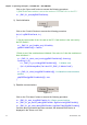
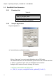
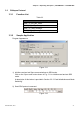
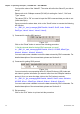
2) Input the servo to change (Including Node ID, Group No. and Index value)
Figure 3.8
For example, you can enter the values shown below in Fig. 3.8.
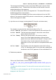
1st field - “Node ID”: If the value is 1, then it will operate the servo with Node ID 1.
2nd field - “Slot ID”: This field cannot be changed. It shows the current Slave
device (Servo's Slot ID is 0).
3rd Field - “Group”: Refers to the group number. of the device (usually a
servo). For a more detailed description of group number,
please refer to the “ASDA-A2 User Manual”. If Group is set to
0 as shown in Fig. 3.8, this means this will set the servo
parameter for “P0-xx” (the value of xx is explained below under
Index).
4th field - “Index”: As noted above, this value depends on the value for Group.
In Fig. 3.8, index has a value of 0 so in this case, read/write will
be carried on the “P0-00” parameter of Servo with Node ID of 1.
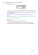
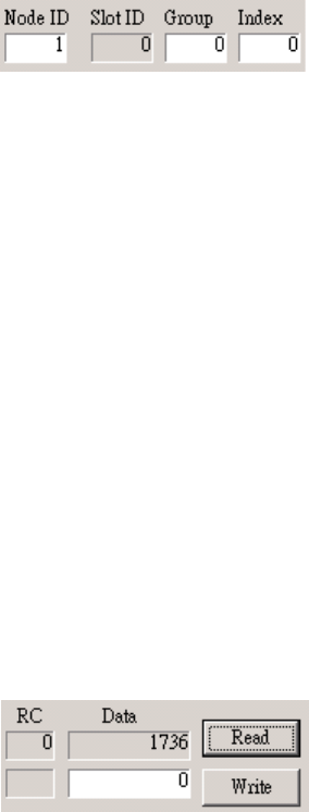
3) Read servo parameter
Figure 3.9
Click on the “Read” button to execute the following procedure:
rt = _DMC_01_read_servo_parameter(gDMCCardNo, NodeID, SlotID, group, idx,
&data);
// A data value will be returned. The value will be current value set for this servo
parameter.
// The value of rt will be displayed in the “RC” field while the value of data will be
displayed in the “Data” field.