
Human Machine Interface User Manual
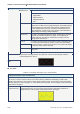
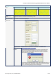
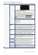
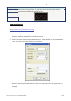
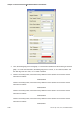
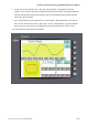
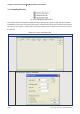
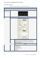
Table Of Contents
- Cover
- Preface
- Table of Contents
- Chapter 1 Introduction
- Chapter 2 Creating and Editing Screens
- 2.1 ScrEdit (Screen Editor) Setup
- 2.2 How to Start ScrEdit
- 2.3 Menu Bar and Toolbar (File)
- 2.4 Menu Bar and Toolbar (Edit)
- 2.5 Menu Bar and Toolbar (View)
- 2.6 Menu Bar and Toolbar (Element)
- 2.7 Menu Bar and Toolbar (Screen)
- 2.8 Menu Bar and Toolbar (Tools)
- 2.9 Menu Bar and Toolbar (Options)
- 2.10 Menu Bar and Toolbar (Window)
- 2.11 Menu Bar and Toolbar (Help)
- Chapter 3 Element Function
- Chapter 4 Macro Function
- Chapter 5 Control Block and Status Block
- Chapter 6 Internal Memory
- Chapter 7 Example Explanation
- Appendix A Specifications and Installation
- Appendix B USB Flash Drive Function
- Appendix C Main Menu Operation of HMI System
Chapter 3 Element Function|ScrEdit Software User Manual
Revision Apr. 30th, 2007, 2007PDD23000002 3-57
Property Description of X-Y Chart Element
Grid Color
Horiz. Line Number
Vert. Line Number
Please refer to the figure below. The grid color is set to red and the grid number in
horizontal and vertical direction are both set to 2.
Curve Element Example
This curve element example can be downloaded via the following link:
http://59.120.64.39:81/phpbb2/files/curve.dop
1. Please choose Options > Configuration on the menu bar to find the Standard tab in Configuration
dialog box and set the address of the control block as $1000.
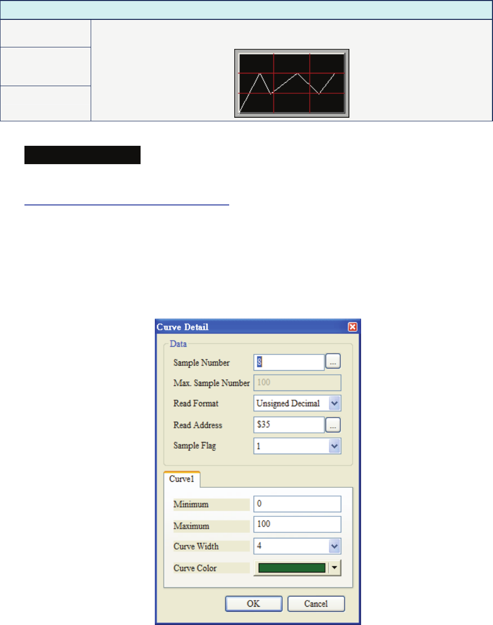
2. Create a trend graph element. Set the Sample Flag to 1, Sample Number to 8, and Read Address
to $35. Your Screen will look like the figure shown below.
3. Create a X-Y chart element. Set the Sample Flag to 2, Sample Number to 7, Horizontal Read
Address to $43 and Vertical Read Address to $50. Your Screen will look like the figure shown on
next page.