
Human Machine Interface User Manual
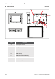

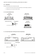
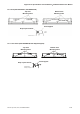

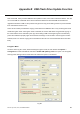
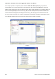
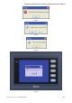
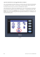
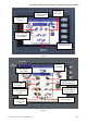
Table Of Contents
- Cover
- Preface
- Table of Contents
- Chapter 1 Introduction
- Chapter 2 Creating and Editing Screens
- 2.1 ScrEdit (Screen Editor) Setup
- 2.2 How to Start ScrEdit
- 2.3 Menu Bar and Toolbar (File)
- 2.4 Menu Bar and Toolbar (Edit)
- 2.5 Menu Bar and Toolbar (View)
- 2.6 Menu Bar and Toolbar (Element)
- 2.7 Menu Bar and Toolbar (Screen)
- 2.8 Menu Bar and Toolbar (Tools)
- 2.9 Menu Bar and Toolbar (Options)
- 2.10 Menu Bar and Toolbar (Window)
- 2.11 Menu Bar and Toolbar (Help)
- Chapter 3 Element Function
- Chapter 4 Macro Function
- Chapter 5 Control Block and Status Block
- Chapter 6 Internal Memory
- Chapter 7 Example Explanation
- Appendix A Specifications and Installation
- Appendix B USB Flash Drive Function
- Appendix C Main Menu Operation of HMI System
Appendix A Specifications and Installation|ScrEdit Software User Manual
A-10 Revision Apr. 30th, 2007, 2007PDD23000002
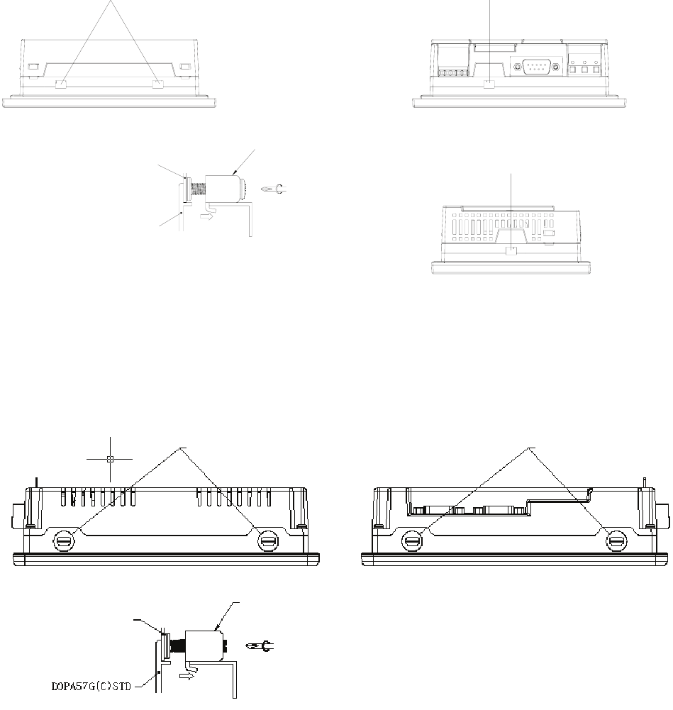
A.3 Installation
Install the fixed support from the internal side of HMI.
1. Do not turn the screw more than its torque specification to avoid damage to plastic box.
2. Damage may occur if torque exceeds 0.7N.M
3.8” Panel (DOP-AS38BSTD(-W))
DOPAS38BSTD(-W)
5.7” Panel (DOP-A(E)57GSTD, DOP-A(E)57CSTD,DOP-A(E)57BSTD)
Top View
Mounting holes
Bottom View
Mounting holes
Fixed support
Snap-in panel mount
Top View
Mounting holes
Bottom View
Mounting hole
Fixed support
Snap-in panel mount
Side View
Mounting hole