
Network Device Product Manual
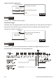
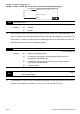
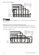
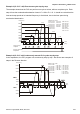

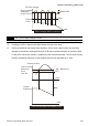
Table Of Contents
- Preface
- Table of Contents
- Chapter 1 Introduction
- Chapter 2 Installation and Wiring
- Chapter 3 Start Up
- Chapter 4 Digital Keypad Operation
- Chapter 5 Parameters
- 5.1 Summary of Parameter Settings
- Group 0 User Parameters
- Group 1 Basic Parameters
- Group 2 Operation Method Parameters
- Group 3 Output Function Parameters
- Group 4 Input Function Parameters
- Group 5 Multi-Step Speed and PLC Parameters
- Group 6 Protection Parameters
- Group 7 Motor Parameters
- Group 8 Special Parameters
- Group 9 Communication Parameters
- Group A PID Parameters
- 5.2 Parameter Settings for Applications
- 5.3 Description of Parameter Settings
- Group 0: User Parameters
- Group 1: Basic Parameters
- Group 2: Operation Method Parameters
- Group 3: Output Function Parameters
- Group 4: Input Function Parameters
- Group 5: Multi-step Speeds and PLC (Process Logic Control) Parameters
- Group 6: Protection Parameters
- Group 7: Motor Parameters
- Group 8: Special Parameters
- Group 9: Communication Parameters
- Group A: PID Control
- 5.1 Summary of Parameter Settings
- Chapter 6 Fault Code Information
- Chapter 7 Troubleshooting
- 7.1 Over Current (OC)
- 7.2 Ground Fault
- 7.3 Over Voltage (OV)
- 7.4 Low Voltage (Lv)
- 7.5 Over Heat (OH)
- 7.6 Overload
- 7.7 Keypad Display is Abnormal
- 7.8 Phase Loss (PHL)
- 7.9 Motor cannot Run
- 7.10 Motor Speed cannot be Changed
- 7.11 Motor Stalls during Acceleration
- 7.12 The Motor does not Run as Expected
- 7.13 Electromagnetic/Induction Noise
- 7.14 Environmental Condition
- 7.15 Affecting Other Machines
- Chapter 8 Maintenance and Inspections
- Appendix A Specifications
- Appendix B Accessories
- Appendix C How to Select the Right AC Motor Drive

Chapter 5 Parameters|VFD-S Series
Revision August 2008, SE09, SW V2.61 5-53
DC bus voltage
time
Over-voltage
detection
level Pr.6-01
Output
Freq.
time
Over-voltage Stall Prevention
Band=20V
6-02
Over-Current Stall Prevention Level
Unit: 1
Settings d20 to d150% Factory Setting: d130
A setting of 100% is equal to the Rated Output Current of the drive.
During acceleration and steady-state operation, the AC drive output current may increase
abruptly to exceed the value specified by Pr.6-02 due to rapid acceleration or excessive load
on the motor. When this function is enabled, the AC drive will decrease. The AC drive will only
resume acceleration when the current drops below the level specified by Pr. 6-02.
Output current
Over-current
detection
level
Pr.6-02
time
Output
frequency
time
Over-current Stall Prevention Level
ON
OFF
Band=5%