
Network Device Product Manual

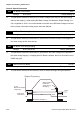

Table Of Contents
- Preface
- Table of Contents
- Chapter 1 Introduction
- Chapter 2 Installation and Wiring
- Chapter 3 Start Up
- Chapter 4 Digital Keypad Operation
- Chapter 5 Parameters
- 5.1 Summary of Parameter Settings
- Group 0 User Parameters
- Group 1 Basic Parameters
- Group 2 Operation Method Parameters
- Group 3 Output Function Parameters
- Group 4 Input Function Parameters
- Group 5 Multi-Step Speed and PLC Parameters
- Group 6 Protection Parameters
- Group 7 Motor Parameters
- Group 8 Special Parameters
- Group 9 Communication Parameters
- Group A PID Parameters
- 5.2 Parameter Settings for Applications
- 5.3 Description of Parameter Settings
- Group 0: User Parameters
- Group 1: Basic Parameters
- Group 2: Operation Method Parameters
- Group 3: Output Function Parameters
- Group 4: Input Function Parameters
- Group 5: Multi-step Speeds and PLC (Process Logic Control) Parameters
- Group 6: Protection Parameters
- Group 7: Motor Parameters
- Group 8: Special Parameters
- Group 9: Communication Parameters
- Group A: PID Control
- 5.1 Summary of Parameter Settings
- Chapter 6 Fault Code Information
- Chapter 7 Troubleshooting
- 7.1 Over Current (OC)
- 7.2 Ground Fault
- 7.3 Over Voltage (OV)
- 7.4 Low Voltage (Lv)
- 7.5 Over Heat (OH)
- 7.6 Overload
- 7.7 Keypad Display is Abnormal
- 7.8 Phase Loss (PHL)
- 7.9 Motor cannot Run
- 7.10 Motor Speed cannot be Changed
- 7.11 Motor Stalls during Acceleration
- 7.12 The Motor does not Run as Expected
- 7.13 Electromagnetic/Induction Noise
- 7.14 Environmental Condition
- 7.15 Affecting Other Machines
- Chapter 8 Maintenance and Inspections
- Appendix A Specifications
- Appendix B Accessories
- Appendix C How to Select the Right AC Motor Drive

Chapter 5 Parameters|VFD-S Series
5-58 Revision August 2008, SE09, SW V2.61
Group 8: Special Parameters
8-00 DC Brake Current Level Unit: 1
Settings d0 to d30% Factory Setting: d0
This parameter determines the level of DC Brake Voltage Level output to the motor during
start-up and stopping. When setting DC Brake Voltage, the Maximum Output Voltage (Pr.1-
02) is regarded as 100%. It is recommended to start with a low DC Brake Voltage Level and
then increase until proper holding torque has been attained.
8-01 DC Brake Time during Start-up Unit: 0.1
Settings d0.0 to d60.0 sec Factory Setting: d0.0
This parameter determines the duration of time that the DC Brake Current will be applied to
the motor during the AC drive start-up.
8-02 DC Brake Time during Stopping Unit: 0.1
Settings d0.0 to d60.0 sec Factory Setting: d0.0
This parameter determines the duration of time that the DC brake voltage will be applied to
the motor during stopping. If stopping with DC Brake is desired, then Pr.2-02 must be set to
RAMP stop (d0).
8-03 Start-Point for DC Brake Unit: 0.1
Settings d0.0 to d400Hz Factory Setting: d0.0
This parameter determines the frequency when DC Brake will begin during deceleration.
Operation
Command
ON
OFF
01-05
08-03
Output Frequency
Minimum Output
Frequency
Start-Point for
DC Brake
Time during
Stopping
DC Brake Voltage %
Time
08-01
08-02