
Network Device Product Manual
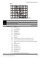

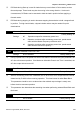
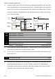

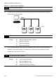
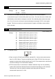
Table Of Contents
- Preface
- Table of Contents
- Chapter 1 Introduction
- Chapter 2 Installation and Wiring
- Chapter 3 Start Up
- Chapter 4 Digital Keypad Operation
- Chapter 5 Parameters
- 5.1 Summary of Parameter Settings
- Group 0 User Parameters
- Group 1 Basic Parameters
- Group 2 Operation Method Parameters
- Group 3 Output Function Parameters
- Group 4 Input Function Parameters
- Group 5 Multi-Step Speed and PLC Parameters
- Group 6 Protection Parameters
- Group 7 Motor Parameters
- Group 8 Special Parameters
- Group 9 Communication Parameters
- Group A PID Parameters
- 5.2 Parameter Settings for Applications
- 5.3 Description of Parameter Settings
- Group 0: User Parameters
- Group 1: Basic Parameters
- Group 2: Operation Method Parameters
- Group 3: Output Function Parameters
- Group 4: Input Function Parameters
- Group 5: Multi-step Speeds and PLC (Process Logic Control) Parameters
- Group 6: Protection Parameters
- Group 7: Motor Parameters
- Group 8: Special Parameters
- Group 9: Communication Parameters
- Group A: PID Control
- 5.1 Summary of Parameter Settings
- Chapter 6 Fault Code Information
- Chapter 7 Troubleshooting
- 7.1 Over Current (OC)
- 7.2 Ground Fault
- 7.3 Over Voltage (OV)
- 7.4 Low Voltage (Lv)
- 7.5 Over Heat (OH)
- 7.6 Overload
- 7.7 Keypad Display is Abnormal
- 7.8 Phase Loss (PHL)
- 7.9 Motor cannot Run
- 7.10 Motor Speed cannot be Changed
- 7.11 Motor Stalls during Acceleration
- 7.12 The Motor does not Run as Expected
- 7.13 Electromagnetic/Induction Noise
- 7.14 Environmental Condition
- 7.15 Affecting Other Machines
- Chapter 8 Maintenance and Inspections
- Appendix A Specifications
- Appendix B Accessories
- Appendix C How to Select the Right AC Motor Drive

Chapter 5 Parameters|VFD-S Series
Revision August 2008, SE09, SW V2.61 5-63
9-03 Time-out Detection
Factory Setting: d0
Settings d0 Disable
d1~d20 1~20 sec
If this function is enabled, the timer will start counting once the first valid Modbus
communication signal is received after power-up or reset. The timer will reset to 0 after each
valid Modbus communication message is received. If the watchdog timer reaches the value
set in Pr. 9-03, the drive will stop its output and display the message "CE10" on the digital
keypad. This fault can reset by an external terminal, keypad or a Modbus communication
reset command.
9-04 Communication Protocol
Factory Setting: d0
Settings d0 Modbus ASCII mode, protocol <7,N,2>
d1 Modbus ASCII mode, protocol <7,E,1>
d2 Modbus ASCII mode, protocol <7,O,1>
d3 Modbus ASCII mode, protocol <8,N,2>
d4 Modbus ASCII mode, protocol <8,E,1>
d5 Modbus ASCII mode, protocol <8,O,1>
d6 Modbus RTU mode, protocol <8,N,2>
d7 Modbus RTU mode, protocol <8,E,1>
d8 Modbus RTU mode, protocol <8,O,1>
1. Computer Control
6
1
1: +EV
2: GND
3: SG-
4: SG+
There is a built-in RS-485 serial interface, marked (RJ-11 Jack) on the control terminal
block, for VFD-S Series. The pins are defined above. Each VFD-S AC drive has a pre-
assigned communication address specified by Pr. 9-00. The computer then controls each
AC drive according to its communication address.
VFD-S can be setup to communicate on Modbus networks using one of the following
modes: ASCII (American Standard Code for Information Interchange) or RTU (Remote
Terminal Unit). Users can select the desired mode along with the serial port
communication protocol in Pr. 9-04.