
Network Device Product Manual
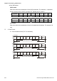
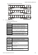
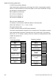
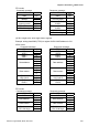
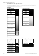

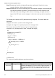
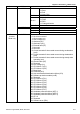
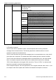
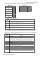
Table Of Contents
- Preface
- Table of Contents
- Chapter 1 Introduction
- Chapter 2 Installation and Wiring
- Chapter 3 Start Up
- Chapter 4 Digital Keypad Operation
- Chapter 5 Parameters
- 5.1 Summary of Parameter Settings
- Group 0 User Parameters
- Group 1 Basic Parameters
- Group 2 Operation Method Parameters
- Group 3 Output Function Parameters
- Group 4 Input Function Parameters
- Group 5 Multi-Step Speed and PLC Parameters
- Group 6 Protection Parameters
- Group 7 Motor Parameters
- Group 8 Special Parameters
- Group 9 Communication Parameters
- Group A PID Parameters
- 5.2 Parameter Settings for Applications
- 5.3 Description of Parameter Settings
- Group 0: User Parameters
- Group 1: Basic Parameters
- Group 2: Operation Method Parameters
- Group 3: Output Function Parameters
- Group 4: Input Function Parameters
- Group 5: Multi-step Speeds and PLC (Process Logic Control) Parameters
- Group 6: Protection Parameters
- Group 7: Motor Parameters
- Group 8: Special Parameters
- Group 9: Communication Parameters
- Group A: PID Control
- 5.1 Summary of Parameter Settings
- Chapter 6 Fault Code Information
- Chapter 7 Troubleshooting
- 7.1 Over Current (OC)
- 7.2 Ground Fault
- 7.3 Over Voltage (OV)
- 7.4 Low Voltage (Lv)
- 7.5 Over Heat (OH)
- 7.6 Overload
- 7.7 Keypad Display is Abnormal
- 7.8 Phase Loss (PHL)
- 7.9 Motor cannot Run
- 7.10 Motor Speed cannot be Changed
- 7.11 Motor Stalls during Acceleration
- 7.12 The Motor does not Run as Expected
- 7.13 Electromagnetic/Induction Noise
- 7.14 Environmental Condition
- 7.15 Affecting Other Machines
- Chapter 8 Maintenance and Inspections
- Appendix A Specifications
- Appendix B Accessories
- Appendix C How to Select the Right AC Motor Drive
Chapter 5 Parameters|VFD-S Series
Revision August 2008, SE09, SW V2.61 5-65
2.2 11-bit character frame (For 8-bit character):
Start
bit
0123456
Stop
bit
Stop
bit
8-bit character
11-bit character frame
( 8.N.2 )
Start
bit
01234
5
6
Even
p
arity
Stop
bit
11-bit character frame
( 8.E .1 )
Start
bit
01234
5
6
Stop
bit
11-bit character frame
( 8.O.1 )
Odd
parity
7
7
7
8-bit character
8-bit character
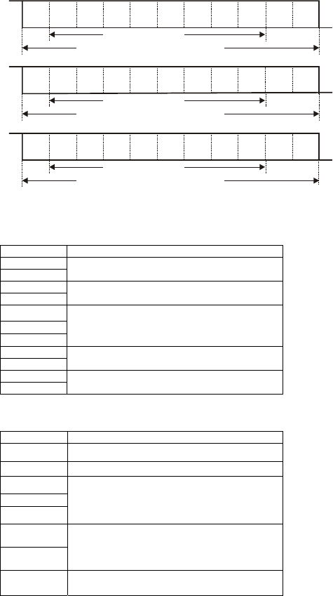
3. Communication Protocol
3.1 Communication Data Frame:
ASCII mode:
STX Start character ‘:’ (3AH)
ADR 1
ADR 0
Communication address:
8-bit address consists of 2 ASCII codes
CMD1
CMD0
Command code:
8-bit command consists of 2 ASCII codes
DATA (n-1)
…….
DATA 0
Contents of data:
n x 8-bit data consist of 2n ASCII codes.
n <= 25,maximum of 50 ASCII codes
LRC CHK 1
LRC CHK 0
LRC check sum:
8-bit check sum consists of 2 ASCII codes
END1
END0
End characters:
END1= CR (0DH), END0= LF (0AH)
RTU mode:
START A silent interval of more than 10 ms
ADR Communication address: 8-bit address
CMD Command code: 8-bit command
DATA (n-1)
…….
DATA 0
Contents of data:
n x 8-bit data, n<= 25
CRC CHK
Low
CRC CHK
High
CRC check sum:
16-bit check sum consists of 2 8-bit characters
END A silent interval of more than 10 ms