
Network Device Product Manual
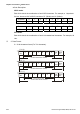
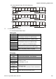
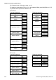

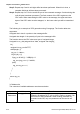
Table Of Contents
- Preface
- Table of Contents
- Chapter 1 Introduction
- Chapter 2 Installation and Wiring
- Chapter 3 Start Up
- Chapter 4 Digital Keypad Operation
- Chapter 5 Parameters
- 5.1 Summary of Parameter Settings
- Group 0 User Parameters
- Group 1 Basic Parameters
- Group 2 Operation Method Parameters
- Group 3 Output Function Parameters
- Group 4 Input Function Parameters
- Group 5 Multi-Step Speed and PLC Parameters
- Group 6 Protection Parameters
- Group 7 Motor Parameters
- Group 8 Special Parameters
- Group 9 Communication Parameters
- Group A PID Parameters
- 5.2 Parameter Settings for Applications
- 5.3 Description of Parameter Settings
- Group 0: User Parameters
- Group 1: Basic Parameters
- Group 2: Operation Method Parameters
- Group 3: Output Function Parameters
- Group 4: Input Function Parameters
- Group 5: Multi-step Speeds and PLC (Process Logic Control) Parameters
- Group 6: Protection Parameters
- Group 7: Motor Parameters
- Group 8: Special Parameters
- Group 9: Communication Parameters
- Group A: PID Control
- 5.1 Summary of Parameter Settings
- Chapter 6 Fault Code Information
- Chapter 7 Troubleshooting
- 7.1 Over Current (OC)
- 7.2 Ground Fault
- 7.3 Over Voltage (OV)
- 7.4 Low Voltage (Lv)
- 7.5 Over Heat (OH)
- 7.6 Overload
- 7.7 Keypad Display is Abnormal
- 7.8 Phase Loss (PHL)
- 7.9 Motor cannot Run
- 7.10 Motor Speed cannot be Changed
- 7.11 Motor Stalls during Acceleration
- 7.12 The Motor does not Run as Expected
- 7.13 Electromagnetic/Induction Noise
- 7.14 Environmental Condition
- 7.15 Affecting Other Machines
- Chapter 8 Maintenance and Inspections
- Appendix A Specifications
- Appendix B Accessories
- Appendix C How to Select the Right AC Motor Drive
Chapter 5 Parameters|VFD-S Series
5-68 Revision August 2008, SE09, SW V2.61
(3) Command code: 10H, write n word, n<=12
For example, writing 6000(1770H) to Pr 5-00 (address 0500H) and1000(03E8H) to Pr 5-
01 (address 0501H) with slave address 01H.
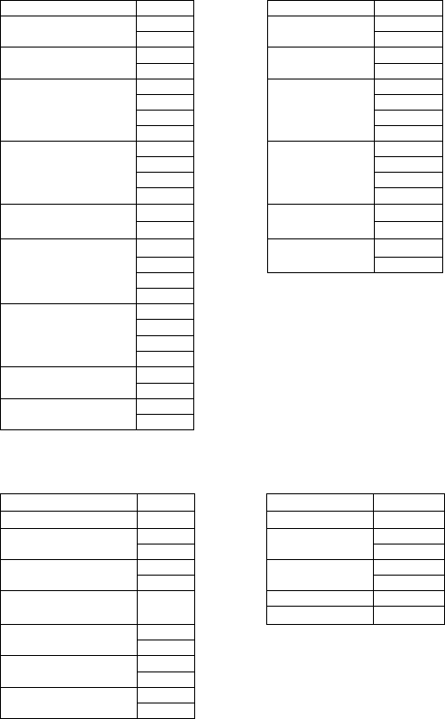
ASCII Mode:
Command message: Response message:
STX ‘:’ STX ‘:’
ADR 1 ‘0’ ADR 1 ‘0’
ADR 0 ‘1’ ADR 0 ‘1’
CMD1 ‘1’ CMD1 ‘1’
CMD0 ‘0’ CMD0 ‘0’
‘0’ ‘0’
‘5’ ‘5’
‘0’ ‘0’
Starting Data address
‘0’
Starting Data
address
‘0’
‘0’ ‘0’
‘0’ ‘0’
‘0’ ‘0’
Number of data
(count by word)
‘2’
Number of data
(count by word)
‘2’
‘0’ LRC CHK 1 ‘E’ Number of data
(count by byte)
‘4’ LRC CHK 0 ‘8’
‘1’ END1 CR
‘7’ END0 LF
‘7’
Data content of
address 0500H
‘0’
‘0’
‘3’
‘E’
Data content of
address 0501H
‘8’
LRC CHK 1 ‘7
LRC CHK 0 ‘2
END1 CR
END0 LF
RTU mode:
Command message: Response message:
ADR 01H ADR 01H
CMD 10H CMD 10H
05H 05H Starting Data address
00H
Starting Data
address
00H
00H 00H Number of data
(count by word)
02H
Number of data
(count by word)
02H
CRC CHK Low 41H Number of data
(count by Byte)
04H
CRC CHK High 04H
17H Data content of
address 0500H
70H
03H Data content of
address 0501H
E8H
CRC CHK Low C8H
CRC CHK High 2EH