
Network Device Product Manual


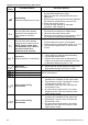
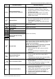
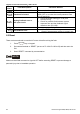
Table Of Contents
- Preface
- Table of Contents
- Chapter 1 Introduction
- Chapter 2 Installation and Wiring
- Chapter 3 Start Up
- Chapter 4 Digital Keypad Operation
- Chapter 5 Parameters
- 5.1 Summary of Parameter Settings
- Group 0 User Parameters
- Group 1 Basic Parameters
- Group 2 Operation Method Parameters
- Group 3 Output Function Parameters
- Group 4 Input Function Parameters
- Group 5 Multi-Step Speed and PLC Parameters
- Group 6 Protection Parameters
- Group 7 Motor Parameters
- Group 8 Special Parameters
- Group 9 Communication Parameters
- Group A PID Parameters
- 5.2 Parameter Settings for Applications
- 5.3 Description of Parameter Settings
- Group 0: User Parameters
- Group 1: Basic Parameters
- Group 2: Operation Method Parameters
- Group 3: Output Function Parameters
- Group 4: Input Function Parameters
- Group 5: Multi-step Speeds and PLC (Process Logic Control) Parameters
- Group 6: Protection Parameters
- Group 7: Motor Parameters
- Group 8: Special Parameters
- Group 9: Communication Parameters
- Group A: PID Control
- 5.1 Summary of Parameter Settings
- Chapter 6 Fault Code Information
- Chapter 7 Troubleshooting
- 7.1 Over Current (OC)
- 7.2 Ground Fault
- 7.3 Over Voltage (OV)
- 7.4 Low Voltage (Lv)
- 7.5 Over Heat (OH)
- 7.6 Overload
- 7.7 Keypad Display is Abnormal
- 7.8 Phase Loss (PHL)
- 7.9 Motor cannot Run
- 7.10 Motor Speed cannot be Changed
- 7.11 Motor Stalls during Acceleration
- 7.12 The Motor does not Run as Expected
- 7.13 Electromagnetic/Induction Noise
- 7.14 Environmental Condition
- 7.15 Affecting Other Machines
- Chapter 8 Maintenance and Inspections
- Appendix A Specifications
- Appendix B Accessories
- Appendix C How to Select the Right AC Motor Drive
Chapter 6 Fault Code Information|VFD-S Series
6-4 Revision August 2008, SE09, SW V2.61
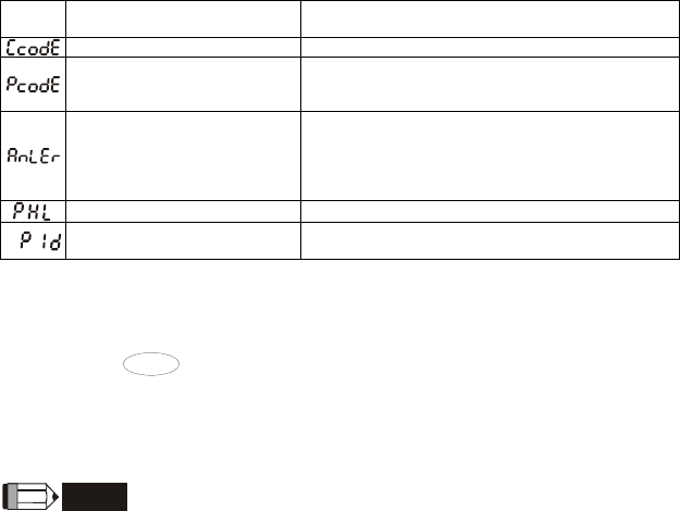
Fault
Name
Fault Descriptions Corrective Actions
Software protection failure Return to the factory.
Password is locked.
Keypad will be locked. Turn the power ON after
power OFF to re-enter the correct password. See
Pr.0-07 and 0-08.
Analog feedback error or
ACI open circuit
1. Check parameter setting (Pr.A-00) and
AVI/ACI wiring
2. Check for possible fault between system
response time and the feedback signal
detection time (Pr.A-08).
Phase Loss Check input phase wiring for loose contacts.
PID feedback error
1. Check PID feedback wiring.
2. Check if the parameter setting is properly set.
6.2 Reset
There are three methods to reset the AC motor drive after solving the fault:
1. Press
STOP/RESET
key on keypad.
2. Set external terminal to “RESET” (set one of Pr.4-04~Pr.4-08 to 06) and then set to be
ON.
3. Send “RESET” command by communication.
NOTE
Make sure that RUN command or signal is OFF before executing RESET to prevent damage or
personal injury due to immediate operation.