
Network Device Product Manual
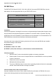

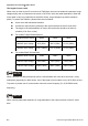


Table Of Contents
- Preface
- Table of Contents
- Chapter 1 Introduction
- Chapter 2 Installation and Wiring
- Chapter 3 Start Up
- Chapter 4 Digital Keypad Operation
- Chapter 5 Parameters
- 5.1 Summary of Parameter Settings
- Group 0 User Parameters
- Group 1 Basic Parameters
- Group 2 Operation Method Parameters
- Group 3 Output Function Parameters
- Group 4 Input Function Parameters
- Group 5 Multi-Step Speed and PLC Parameters
- Group 6 Protection Parameters
- Group 7 Motor Parameters
- Group 8 Special Parameters
- Group 9 Communication Parameters
- Group A PID Parameters
- 5.2 Parameter Settings for Applications
- 5.3 Description of Parameter Settings
- Group 0: User Parameters
- Group 1: Basic Parameters
- Group 2: Operation Method Parameters
- Group 3: Output Function Parameters
- Group 4: Input Function Parameters
- Group 5: Multi-step Speeds and PLC (Process Logic Control) Parameters
- Group 6: Protection Parameters
- Group 7: Motor Parameters
- Group 8: Special Parameters
- Group 9: Communication Parameters
- Group A: PID Control
- 5.1 Summary of Parameter Settings
- Chapter 6 Fault Code Information
- Chapter 7 Troubleshooting
- 7.1 Over Current (OC)
- 7.2 Ground Fault
- 7.3 Over Voltage (OV)
- 7.4 Low Voltage (Lv)
- 7.5 Over Heat (OH)
- 7.6 Overload
- 7.7 Keypad Display is Abnormal
- 7.8 Phase Loss (PHL)
- 7.9 Motor cannot Run
- 7.10 Motor Speed cannot be Changed
- 7.11 Motor Stalls during Acceleration
- 7.12 The Motor does not Run as Expected
- 7.13 Electromagnetic/Induction Noise
- 7.14 Environmental Condition
- 7.15 Affecting Other Machines
- Chapter 8 Maintenance and Inspections
- Appendix A Specifications
- Appendix B Accessories
- Appendix C How to Select the Right AC Motor Drive
Appendix B Accessories|VFD-S Series
Revision August 2008, SE09, SW V2.61 B-5
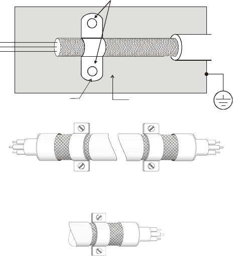
1. Use the cable with shielding (double shielding is the best).
2. The shielding on both ends of the motor cable should be grounded with the minimum
length and maximum contact area.
3. Remove any paint on metal saddle for good ground contact with the plate and shielding.
Remove any paint on metal saddle for good ground contact with
the plate and shielding.
saddle
the plate with grounding
Saddle on both ends
Saddle on one end