
Network Device Product Manual
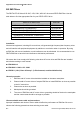

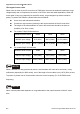
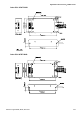


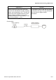
Table Of Contents
- Preface
- Table of Contents
- Chapter 1 Introduction
- Chapter 2 Installation and Wiring
- Chapter 3 Start Up
- Chapter 4 Digital Keypad Operation
- Chapter 5 Parameters
- 5.1 Summary of Parameter Settings
- Group 0 User Parameters
- Group 1 Basic Parameters
- Group 2 Operation Method Parameters
- Group 3 Output Function Parameters
- Group 4 Input Function Parameters
- Group 5 Multi-Step Speed and PLC Parameters
- Group 6 Protection Parameters
- Group 7 Motor Parameters
- Group 8 Special Parameters
- Group 9 Communication Parameters
- Group A PID Parameters
- 5.2 Parameter Settings for Applications
- 5.3 Description of Parameter Settings
- Group 0: User Parameters
- Group 1: Basic Parameters
- Group 2: Operation Method Parameters
- Group 3: Output Function Parameters
- Group 4: Input Function Parameters
- Group 5: Multi-step Speeds and PLC (Process Logic Control) Parameters
- Group 6: Protection Parameters
- Group 7: Motor Parameters
- Group 8: Special Parameters
- Group 9: Communication Parameters
- Group A: PID Control
- 5.1 Summary of Parameter Settings
- Chapter 6 Fault Code Information
- Chapter 7 Troubleshooting
- 7.1 Over Current (OC)
- 7.2 Ground Fault
- 7.3 Over Voltage (OV)
- 7.4 Low Voltage (Lv)
- 7.5 Over Heat (OH)
- 7.6 Overload
- 7.7 Keypad Display is Abnormal
- 7.8 Phase Loss (PHL)
- 7.9 Motor cannot Run
- 7.10 Motor Speed cannot be Changed
- 7.11 Motor Stalls during Acceleration
- 7.12 The Motor does not Run as Expected
- 7.13 Electromagnetic/Induction Noise
- 7.14 Environmental Condition
- 7.15 Affecting Other Machines
- Chapter 8 Maintenance and Inspections
- Appendix A Specifications
- Appendix B Accessories
- Appendix C How to Select the Right AC Motor Drive
Appendix B Accessories|VFD-S Series
B-12 Revision August 2008, SE09, SW V2.61
B.3.3 Applications for AC Reactor
Connected in input circuit
Application 1
Question
When more than one AC motor drive is
connected to the same mains power, and one
of them is ON during operation.
When applying power to one of the AC motor
drive, the charge current of the capacitors
may cause voltage dip. The AC motor drive
may be damaged when over current occurs
during operation.
Correct wiring
M1
M2
Mn
reactor
AC motor drive
AC motor drive
AC motor drive
motor
motor
motor
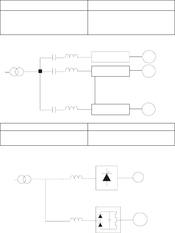
Application 2 Question
Silicon rectifier and AC motor drive are
connected to the same power.
Switching spikes will be generated when the
silicon rectifier switches on/off. These spikes
may damage the mains circuit.
Correct wiring
DC
power
reactor
reactor
AC motor drive
motor
silicon rectifier