
Network Device Product Manual
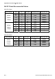
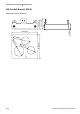
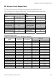
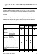
Table Of Contents
- Preface
- Table of Contents
- Chapter 1 Introduction
- Chapter 2 Installation and Wiring
- Chapter 3 Start Up
- Chapter 4 Digital Keypad Operation
- Chapter 5 Parameters
- 5.1 Summary of Parameter Settings
- Group 0 User Parameters
- Group 1 Basic Parameters
- Group 2 Operation Method Parameters
- Group 3 Output Function Parameters
- Group 4 Input Function Parameters
- Group 5 Multi-Step Speed and PLC Parameters
- Group 6 Protection Parameters
- Group 7 Motor Parameters
- Group 8 Special Parameters
- Group 9 Communication Parameters
- Group A PID Parameters
- 5.2 Parameter Settings for Applications
- 5.3 Description of Parameter Settings
- Group 0: User Parameters
- Group 1: Basic Parameters
- Group 2: Operation Method Parameters
- Group 3: Output Function Parameters
- Group 4: Input Function Parameters
- Group 5: Multi-step Speeds and PLC (Process Logic Control) Parameters
- Group 6: Protection Parameters
- Group 7: Motor Parameters
- Group 8: Special Parameters
- Group 9: Communication Parameters
- Group A: PID Control
- 5.1 Summary of Parameter Settings
- Chapter 6 Fault Code Information
- Chapter 7 Troubleshooting
- 7.1 Over Current (OC)
- 7.2 Ground Fault
- 7.3 Over Voltage (OV)
- 7.4 Low Voltage (Lv)
- 7.5 Over Heat (OH)
- 7.6 Overload
- 7.7 Keypad Display is Abnormal
- 7.8 Phase Loss (PHL)
- 7.9 Motor cannot Run
- 7.10 Motor Speed cannot be Changed
- 7.11 Motor Stalls during Acceleration
- 7.12 The Motor does not Run as Expected
- 7.13 Electromagnetic/Induction Noise
- 7.14 Environmental Condition
- 7.15 Affecting Other Machines
- Chapter 8 Maintenance and Inspections
- Appendix A Specifications
- Appendix B Accessories
- Appendix C How to Select the Right AC Motor Drive
Appendix B Accessories|VFD-S Series
Revision August 2008, SE09, SW V2.61 B-19
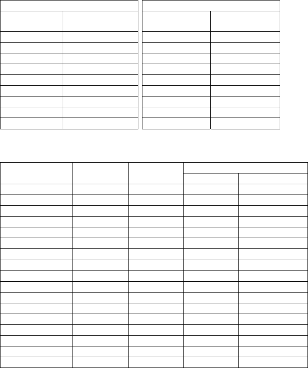
B.9 Non-fuse Circuit Breaker Chart
The fuse should comply with UL248 and the breaker should comply with UL489.
The current rating of the breaker shall be within 2~4 times maximum input current rating.
(Refer to Appendix A for rated input/output current)
1-phase 3-phase
Model
Recommended
non-fuse breaker (A)
Model
Recommended
non-fuse breaker (A)
VFD002S11A/B 15 VFD002S23A 5
VFD002S21A/B/E 10 VFD004S23A 5
VFD004S11A/B 20 VFD004S43A/B/E 5
VFD004S21A/B/E 15 VFD007S23A 10
VFD007S11A/B 30 VFD007S43A/B/E 5
VFD007S21A/B/E 20 VFD015S23D 20
VFD015S21D/E 30 VFD015S43D/E/U 10
VFD022S21D/E/U 50 VFD022S23D 30
VFD022S43D/E/U 15
Fuse Specification Chart
Smaller fuses than those shown in the table are permitted.
Line Fuse
Model I (input)(A) I (output)(A)
I (A) Bussmann P/N
VFD002S11A/B 6 1.6 15 JJN-15
VFD002S21A/B/E 4,9 1.6 10 JJN-10
VFD002S23A 2.4 1.6 5 JJN-6
VFD004S11A/B 9 2.5 20 JJN-20
VFD004S21A/B/E 6.5 2.5 15 JJN-15
VFD004S23A 3.0 2.5 5 JJN-6
VFD004S43A/B/E 1.9 1.5 5 JJN-5
VFD007S11A/B 18 4.2 30 JJN-30
VFD007S21A/B/E 9.7 4.2 20 JJN-20
VFD007S23A 5.1 4.2 10 JJN-10
VFD007S43A/B/E 3.2 2.5 5 JJN-5
VFD015S21D/E 15.7 7.5 30 JJN-30
VFD015S23D 9.0 7.5 20 JJN-20
VFD015S43D/E/U 4.3 4.2 10 JJN-10
VFD022S21D/E/U 24 11.0 50 JJN-50
VFD022S23D 15 11.0 30 JJN-30
VFD022S43D/E/U 7.1 5.5 15 JJN-15