
Network Device Product Manual
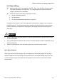
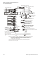
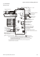
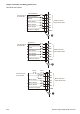

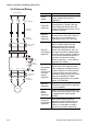


Table Of Contents
- Preface
- Table of Contents
- Chapter 1 Introduction
- Chapter 2 Installation and Wiring
- Chapter 3 Start Up
- Chapter 4 Digital Keypad Operation
- Chapter 5 Parameters
- 5.1 Summary of Parameter Settings
- Group 0 User Parameters
- Group 1 Basic Parameters
- Group 2 Operation Method Parameters
- Group 3 Output Function Parameters
- Group 4 Input Function Parameters
- Group 5 Multi-Step Speed and PLC Parameters
- Group 6 Protection Parameters
- Group 7 Motor Parameters
- Group 8 Special Parameters
- Group 9 Communication Parameters
- Group A PID Parameters
- 5.2 Parameter Settings for Applications
- 5.3 Description of Parameter Settings
- Group 0: User Parameters
- Group 1: Basic Parameters
- Group 2: Operation Method Parameters
- Group 3: Output Function Parameters
- Group 4: Input Function Parameters
- Group 5: Multi-step Speeds and PLC (Process Logic Control) Parameters
- Group 6: Protection Parameters
- Group 7: Motor Parameters
- Group 8: Special Parameters
- Group 9: Communication Parameters
- Group A: PID Control
- 5.1 Summary of Parameter Settings
- Chapter 6 Fault Code Information
- Chapter 7 Troubleshooting
- 7.1 Over Current (OC)
- 7.2 Ground Fault
- 7.3 Over Voltage (OV)
- 7.4 Low Voltage (Lv)
- 7.5 Over Heat (OH)
- 7.6 Overload
- 7.7 Keypad Display is Abnormal
- 7.8 Phase Loss (PHL)
- 7.9 Motor cannot Run
- 7.10 Motor Speed cannot be Changed
- 7.11 Motor Stalls during Acceleration
- 7.12 The Motor does not Run as Expected
- 7.13 Electromagnetic/Induction Noise
- 7.14 Environmental Condition
- 7.15 Affecting Other Machines
- Chapter 8 Maintenance and Inspections
- Appendix A Specifications
- Appendix B Accessories
- Appendix C How to Select the Right AC Motor Drive

Chapter 2 Installation and Wiring|VFD-S Series
Revision August 2008, SE09, SW V2.61 2-17
2.4.1 Basic Wiring
Make sure that power is only applied to the R/L1, S/L2, T/L3 terminals. Failure to comply
may result in damage to the equipment. The voltage and current should lie within the
range as indicated on the nameplate.
Check the following items after completing the wiring:
1. Are all connections correct?
2. No loose wires?
3. No short-circuits between terminals or to ground?
A charge may still remain in the DC bus capacitors with hazardous voltages even if the power
has been turned off. To prevent personal injury, please ensure that the power is turned off and
wait ten minutes for the capacitors to discharge to safe voltage levels before opening the AC
motor drive.
DANGER!
1. All the units must be grounded directly to a common ground terminal to prevent electric shock,
fire and interference.
2. Only qualified personnel familiar with AC motor drives are allowed to perform installation, wiring
and commissioning.
3. Make sure that the power is off before doing any wiring to prevent electric shocks.
Basic Wiring Diagrams
Users must connect wires according to the circuit diagrams on the following pages. Do not plug a
modem or telephone line to the RS-485 communication port or permanent damage may result. Pins
1 & 2 are the power supply for the optional copy keypad only and should not be used for RS-485
communication.