
Network Device Product Manual
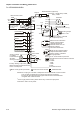
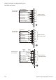

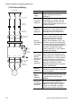


Table Of Contents
- Preface
- Table of Contents
- Chapter 1 Introduction
- Chapter 2 Installation and Wiring
- Chapter 3 Start Up
- Chapter 4 Digital Keypad Operation
- Chapter 5 Parameters
- 5.1 Summary of Parameter Settings
- Group 0 User Parameters
- Group 1 Basic Parameters
- Group 2 Operation Method Parameters
- Group 3 Output Function Parameters
- Group 4 Input Function Parameters
- Group 5 Multi-Step Speed and PLC Parameters
- Group 6 Protection Parameters
- Group 7 Motor Parameters
- Group 8 Special Parameters
- Group 9 Communication Parameters
- Group A PID Parameters
- 5.2 Parameter Settings for Applications
- 5.3 Description of Parameter Settings
- Group 0: User Parameters
- Group 1: Basic Parameters
- Group 2: Operation Method Parameters
- Group 3: Output Function Parameters
- Group 4: Input Function Parameters
- Group 5: Multi-step Speeds and PLC (Process Logic Control) Parameters
- Group 6: Protection Parameters
- Group 7: Motor Parameters
- Group 8: Special Parameters
- Group 9: Communication Parameters
- Group A: PID Control
- 5.1 Summary of Parameter Settings
- Chapter 6 Fault Code Information
- Chapter 7 Troubleshooting
- 7.1 Over Current (OC)
- 7.2 Ground Fault
- 7.3 Over Voltage (OV)
- 7.4 Low Voltage (Lv)
- 7.5 Over Heat (OH)
- 7.6 Overload
- 7.7 Keypad Display is Abnormal
- 7.8 Phase Loss (PHL)
- 7.9 Motor cannot Run
- 7.10 Motor Speed cannot be Changed
- 7.11 Motor Stalls during Acceleration
- 7.12 The Motor does not Run as Expected
- 7.13 Electromagnetic/Induction Noise
- 7.14 Environmental Condition
- 7.15 Affecting Other Machines
- Chapter 8 Maintenance and Inspections
- Appendix A Specifications
- Appendix B Accessories
- Appendix C How to Select the Right AC Motor Drive
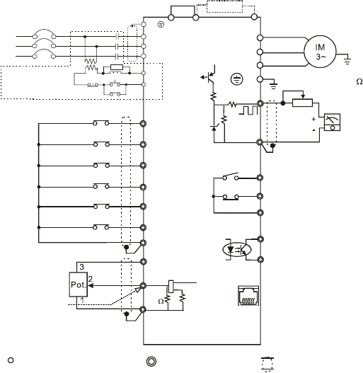
Chapter 2 Installation and Wiring|VFD-S Series
2-18 Revision August 2008, SE09, SW V2.61
For VFDXXXSXXA/B/D/U
47K
Grounding resistance
less than 100
17V
S/L2
T/L3
NFB
SA
OFF
ON
MC
MC
RB
RC
Recommended Circuit
when power supply
is turned OFF by a
fault output
R/L1
R/L1
S/L2
T/L3
E
Brake Resistor (optional)
select 80 120W, 200 120W,
Ω Ω
400 120W
Ω
Main Circuit Power
+1
+2/B1
B2
U/T1
V/T2
W/T3
E
AC Motor
Potentiometer (1K )
Ω
Analog output
DC 0~10V
CPU
2.4K
Ω
47
Ω
AFM
47K
Ω
11V
GND
Factory setting: indicate
output frequency
RA
RB
RC
Multi-function indication
output contacts below
120VAC/24VDC 5A
240VAC less than 2.5A
Factory setting:
indicates malfunction
MO1
MCM
Multi-function Photocoupler
output below 48VDC 50mA
Factory setting: indicates
during operation
RJ-11
6->1
RJ-11 communication port with
RS-485 serial communication interface
1: 17V
2: GND
3: SG-
4: SG+
5: NC
6: Communication
Shielded leads
Factory setting
Forward/Stop
Reverse/Stop
Reset
Multi-step 1
Multi-step 2
Multi-step 3
Common signal
M5
M4
M3
M2
M1
M0
GND
Analog voltage
0~10VDC
Potentiometer
3K~5K
Ω
Analog current
4~20mA
+10V 10mA
(MAX)
1
2
3
250
Ω
AVI
GND
Factory setting: output freq. (Pot.)
determined by the Potentiometer
on the control panel.
Main circuit (power) terminals
Control circuit terminals
NOTE:
Do not plug in a modem or telephone line to the RS-485 communication
port, permanent damage may result. Pins 1&2 are the power
sources for the optional copy keypad and should not be used while
using RS-485 communication.
﹡
If it is single phase model, please select any of the two input power
terminals in main circuit power.
Jumper