
Network Device Product Manual
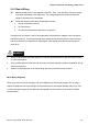
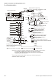
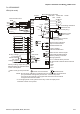
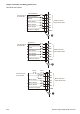

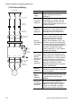
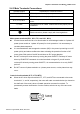


Table Of Contents
- Preface
- Table of Contents
- Chapter 1 Introduction
- Chapter 2 Installation and Wiring
- Chapter 3 Start Up
- Chapter 4 Digital Keypad Operation
- Chapter 5 Parameters
- 5.1 Summary of Parameter Settings
- Group 0 User Parameters
- Group 1 Basic Parameters
- Group 2 Operation Method Parameters
- Group 3 Output Function Parameters
- Group 4 Input Function Parameters
- Group 5 Multi-Step Speed and PLC Parameters
- Group 6 Protection Parameters
- Group 7 Motor Parameters
- Group 8 Special Parameters
- Group 9 Communication Parameters
- Group A PID Parameters
- 5.2 Parameter Settings for Applications
- 5.3 Description of Parameter Settings
- Group 0: User Parameters
- Group 1: Basic Parameters
- Group 2: Operation Method Parameters
- Group 3: Output Function Parameters
- Group 4: Input Function Parameters
- Group 5: Multi-step Speeds and PLC (Process Logic Control) Parameters
- Group 6: Protection Parameters
- Group 7: Motor Parameters
- Group 8: Special Parameters
- Group 9: Communication Parameters
- Group A: PID Control
- 5.1 Summary of Parameter Settings
- Chapter 6 Fault Code Information
- Chapter 7 Troubleshooting
- 7.1 Over Current (OC)
- 7.2 Ground Fault
- 7.3 Over Voltage (OV)
- 7.4 Low Voltage (Lv)
- 7.5 Over Heat (OH)
- 7.6 Overload
- 7.7 Keypad Display is Abnormal
- 7.8 Phase Loss (PHL)
- 7.9 Motor cannot Run
- 7.10 Motor Speed cannot be Changed
- 7.11 Motor Stalls during Acceleration
- 7.12 The Motor does not Run as Expected
- 7.13 Electromagnetic/Induction Noise
- 7.14 Environmental Condition
- 7.15 Affecting Other Machines
- Chapter 8 Maintenance and Inspections
- Appendix A Specifications
- Appendix B Accessories
- Appendix C How to Select the Right AC Motor Drive
Chapter 2 Installation and Wiring|VFD-S Series
Revision August 2008, SE09, SW V2.61 2-25
2.4.4 Control Terminals
Control Terminal Wiring (Factory Setting)
A. XXXSXXA/B/D/U
RA
M1
AVI
10V
+
AFM
M0
M4
M2 M3
M5
GND
RB
RC
MO1
MCM
RJ11
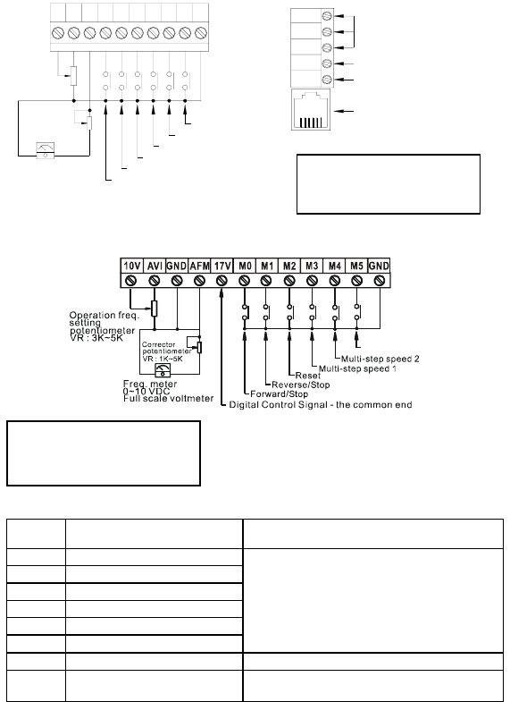
Multi-step speed 3
Multi-step speed 2
Multi-step speed 1
Reset
Reverse/Stop
Forward/Stop
Corrector
potentiometer
VR : 1K~5K
Freq. meter
0~10 VDC
Full scale voltmeter
Operation freq.
setting
potentiometer
VR : 3K~5K
Relay contactor output
Factory setting : Fault indication
Photo coupler output
Factory setting : in work
6 ~ 1
RS485 Communication port
B. XXXSXXE
Multi-step speed 3
*
*
Terminal symbols and functions
Terminal
Symbol
Terminal Function
Factory Settings (NPN mode)
ON: Connect to GND
M0 Multi-function auxiliary input
M1 Multi-function input 1
M2 Multi-function input 2
M3 Multi-function input 3
M4 Multi-function input 4
M5 Multi-function Input 5
Refer to Pr.4-04 to Pr.4-08 for programming
the Multi-function Inputs.
ON: the activation current is 16mA.
OFF: leakage current tolerance is 10
μ
A.
+17V DC Voltage Source +17VDC, 20mA used for PNP mode.
GND Digital Signal Common
Common for digital inputs and used for NPN
mode.
Wire Gauge: 24-12 AWG
Wire Type: Copper Only
Torque: 4 kgf-cm (3.5 in-lbf)
Wire Gauge: 24-16 AWG
Wire Type: Copper Only
Torque: 2 kgf-cm (1.7 in-lbf)