
Network Device Product Manual
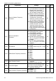
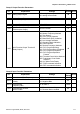
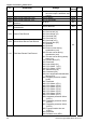

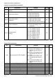


Table Of Contents
- Preface
- Table of Contents
- Chapter 1 Introduction
- Chapter 2 Installation and Wiring
- Chapter 3 Start Up
- Chapter 4 Digital Keypad Operation
- Chapter 5 Parameters
- 5.1 Summary of Parameter Settings
- Group 0 User Parameters
- Group 1 Basic Parameters
- Group 2 Operation Method Parameters
- Group 3 Output Function Parameters
- Group 4 Input Function Parameters
- Group 5 Multi-Step Speed and PLC Parameters
- Group 6 Protection Parameters
- Group 7 Motor Parameters
- Group 8 Special Parameters
- Group 9 Communication Parameters
- Group A PID Parameters
- 5.2 Parameter Settings for Applications
- 5.3 Description of Parameter Settings
- Group 0: User Parameters
- Group 1: Basic Parameters
- Group 2: Operation Method Parameters
- Group 3: Output Function Parameters
- Group 4: Input Function Parameters
- Group 5: Multi-step Speeds and PLC (Process Logic Control) Parameters
- Group 6: Protection Parameters
- Group 7: Motor Parameters
- Group 8: Special Parameters
- Group 9: Communication Parameters
- Group A: PID Control
- 5.1 Summary of Parameter Settings
- Chapter 6 Fault Code Information
- Chapter 7 Troubleshooting
- 7.1 Over Current (OC)
- 7.2 Ground Fault
- 7.3 Over Voltage (OV)
- 7.4 Low Voltage (Lv)
- 7.5 Over Heat (OH)
- 7.6 Overload
- 7.7 Keypad Display is Abnormal
- 7.8 Phase Loss (PHL)
- 7.9 Motor cannot Run
- 7.10 Motor Speed cannot be Changed
- 7.11 Motor Stalls during Acceleration
- 7.12 The Motor does not Run as Expected
- 7.13 Electromagnetic/Induction Noise
- 7.14 Environmental Condition
- 7.15 Affecting Other Machines
- Chapter 8 Maintenance and Inspections
- Appendix A Specifications
- Appendix B Accessories
- Appendix C How to Select the Right AC Motor Drive
Chapter 5 Parameters|VFD-S Series
Revision August 2008, SE09, SW V2.61 5-5
Group 3 Output Function Parameters
Pr. Explanation Settings
Factory
Setting
NOTE
3-00 Analog Output Signal
d0: analog frequency meter
d1: analog current meter
d0
3-01 Analog Output Gain d1 to d200% d100
3-02 Desired Frequency Attained d1.0 to d400 Hz d1.0
3-03 Terminal Count Value d0 to d999 d0
3-04 Preliminary Count Value d0 to d999 d0
3-05
Multi-Function Output Terminal 1
(Photocoupler Output)
d0: No Function d1
3-06
Multi-Function Output Terminal 2
(Relay Output)
d1: AC Drive Operational
d2: Master Frequency Attained
d3: Zero Speed
d4: Over Torque Detection
d5: Base-Block (B.B.) Indication
d6: Low-Voltage Indication
d7: Operation Mode Indication
d8: Fault Indication
d9: Desired Frequency Attained
d10: PLC Program Running
d11: PLC Program Step Completed
d12: PLC Program Completed
d13: PLC Program Operation
Paused
d14: Terminal Count Value Attained
d15: Preliminary Count Value
Attained
d16: AC Motor Drive Ready
d17: FWD command Indication
d18: REV command Indication
d8
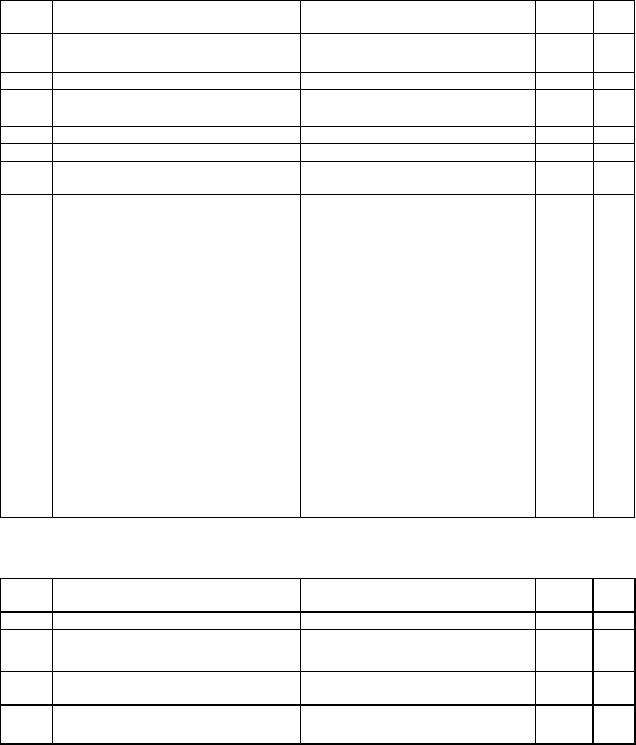
Group 4 Input Function Parameters
Pr. Explanation Settings
Factory
Setting
NOTE
4-00 Potentiometer Bias Frequency d 0.0 to d 100.0% d0.0
4-01
Potentiometer Bias
Polarity
d0: Positive Bias
d1: Negative Bias
d0
4-02
Potentiometer
Frequency Gain
d1 to d200 % d100
4-03
Potentiometer Reverse
Motion Enable
d0: Forward Motion Only
d1: Reverse Motion enabled
d0