
Network Device Product Manual
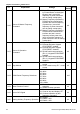
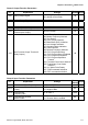
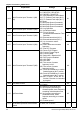
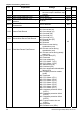

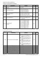


Table Of Contents
- Preface
- Table of Contents
- Chapter 1 Introduction
- Chapter 2 Installation and Wiring
- Chapter 3 Start Up
- Chapter 4 Digital Keypad Operation
- Chapter 5 Parameters
- 5.1 Summary of Parameter Settings
- Group 0 User Parameters
- Group 1 Basic Parameters
- Group 2 Operation Method Parameters
- Group 3 Output Function Parameters
- Group 4 Input Function Parameters
- Group 5 Multi-Step Speed and PLC Parameters
- Group 6 Protection Parameters
- Group 7 Motor Parameters
- Group 8 Special Parameters
- Group 9 Communication Parameters
- Group A PID Parameters
- 5.2 Parameter Settings for Applications
- 5.3 Description of Parameter Settings
- Group 0: User Parameters
- Group 1: Basic Parameters
- Group 2: Operation Method Parameters
- Group 3: Output Function Parameters
- Group 4: Input Function Parameters
- Group 5: Multi-step Speeds and PLC (Process Logic Control) Parameters
- Group 6: Protection Parameters
- Group 7: Motor Parameters
- Group 8: Special Parameters
- Group 9: Communication Parameters
- Group A: PID Control
- 5.1 Summary of Parameter Settings
- Chapter 6 Fault Code Information
- Chapter 7 Troubleshooting
- 7.1 Over Current (OC)
- 7.2 Ground Fault
- 7.3 Over Voltage (OV)
- 7.4 Low Voltage (Lv)
- 7.5 Over Heat (OH)
- 7.6 Overload
- 7.7 Keypad Display is Abnormal
- 7.8 Phase Loss (PHL)
- 7.9 Motor cannot Run
- 7.10 Motor Speed cannot be Changed
- 7.11 Motor Stalls during Acceleration
- 7.12 The Motor does not Run as Expected
- 7.13 Electromagnetic/Induction Noise
- 7.14 Environmental Condition
- 7.15 Affecting Other Machines
- Chapter 8 Maintenance and Inspections
- Appendix A Specifications
- Appendix B Accessories
- Appendix C How to Select the Right AC Motor Drive

Chapter 5 Parameters|VFD-S Series
5-6 Revision August 2008, SE09, SW V2.61
Pr. Explanation Settings
Factory
Setting
NOTE
4-04
Multi-Function Input Terminal 1 (M0,
M1)
d0: No Function
d1: FWD/STOP, REV/STOP
d2: FWD/REV, RUN/STOP
d3: 3-wire Operation Control Mode
d4: E.F. External Fault Input (N.O.)
d5: E.F. External Fault Input (N.C.)
d6: Reset
d7: Multi-Step Speed Command 1
d8: Multi-Step Speed Command 2
d9: Multi-Step Speed Command 3
d1
4-05 Multi-Function Input Terminal 2 (M2)
d10: Jog Operation
d11: Accel/decel Inhibit
d6
4-06 Multi-Function Input Terminal 3 (M3)
d12: First or Second
Acceleration/deceleration Time
Selection
d13: External base block (N.O.)
d14: External base block (N.C.)
d7
4-07 Multi-Function Input Terminal 4 (M4)
d15: Up: Increment master
frequency
d16: Down: Decrement master
frequency
d17: Run PLC Program
d8
4-08 Multi-Function Input Terminal 5 (M5)
d18: Pause PLC Program
d19: Counter Trigger Signal
d20: Counter Reset
d21: Select ACI / Deselect AVI
d22: PID Function Disabled
d23: JOG FWD
d24: JOG REV
d25: The source of master
frequency is AVI.
d26: The source of master
frequency is ACI.
d27: Press UP/DOWN key to switch
forward/reverse (N.O.) motion
d28: Press UP/DOWN key to switch
forward/reverse (N.C.) motion
d29: M0: 0: RUN 1: STOP, M1: no
function, Direction is controlled
by keypad
d9
4-09 Line Start Lockout
d0: Disable
d1: Enable
d0
4-10 Up/Down Mode
d0: Based on accel/decel time
d1: Up frequency according to
constant speed, down frequency
according to deceleration time
d2: Up frequency according to
acceleration time, down
frequenc according to constant
speed
d3: Constant speed
d3
4-11
Accel/Decel Rate of Change of
UP/DOWN Operation with Constant
Speed
0~1000, unit: 5 Hz/sec d1