
Network Device Product Manual
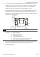


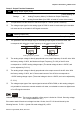
Table Of Contents
- Preface
- Table of Contents
- Chapter 1 Introduction
- Chapter 2 Installation and Wiring
- Chapter 3 Start Up
- Chapter 4 Digital Keypad Operation
- Chapter 5 Parameters
- 5.1 Summary of Parameter Settings
- Group 0 User Parameters
- Group 1 Basic Parameters
- Group 2 Operation Method Parameters
- Group 3 Output Function Parameters
- Group 4 Input Function Parameters
- Group 5 Multi-Step Speed and PLC Parameters
- Group 6 Protection Parameters
- Group 7 Motor Parameters
- Group 8 Special Parameters
- Group 9 Communication Parameters
- Group A PID Parameters
- 5.2 Parameter Settings for Applications
- 5.3 Description of Parameter Settings
- Group 0: User Parameters
- Group 1: Basic Parameters
- Group 2: Operation Method Parameters
- Group 3: Output Function Parameters
- Group 4: Input Function Parameters
- Group 5: Multi-step Speeds and PLC (Process Logic Control) Parameters
- Group 6: Protection Parameters
- Group 7: Motor Parameters
- Group 8: Special Parameters
- Group 9: Communication Parameters
- Group A: PID Control
- 5.1 Summary of Parameter Settings
- Chapter 6 Fault Code Information
- Chapter 7 Troubleshooting
- 7.1 Over Current (OC)
- 7.2 Ground Fault
- 7.3 Over Voltage (OV)
- 7.4 Low Voltage (Lv)
- 7.5 Over Heat (OH)
- 7.6 Overload
- 7.7 Keypad Display is Abnormal
- 7.8 Phase Loss (PHL)
- 7.9 Motor cannot Run
- 7.10 Motor Speed cannot be Changed
- 7.11 Motor Stalls during Acceleration
- 7.12 The Motor does not Run as Expected
- 7.13 Electromagnetic/Induction Noise
- 7.14 Environmental Condition
- 7.15 Affecting Other Machines
- Chapter 8 Maintenance and Inspections
- Appendix A Specifications
- Appendix B Accessories
- Appendix C How to Select the Right AC Motor Drive

Chapter 5 Parameters|VFD-S Series
Revision August 2008, SE09, SW V2.61 5-27
Group 2: Operation Method Parameters
2-00 Source of Master Frequency Command
Factory Setting: d0
Settings d0 Master Frequency input determined by digital keypad. (record the
frequency of power loss and it can do analog overlap plus)
d1 Master Frequency determined by analog signal DC 0V-10V
(external terminal AVI). (won’t record the frequency of power loss
and it can’t do analog overlap plus)
d2 Master Frequency determined by analog signal DC 4mA-20mA
(external terminal AVI). (won’t record the frequency of power loss
and it can’t do analog overlap plus)
d3 Master Frequency determined by Potentiometer on the digital
keypad. (won’t record the frequency of power loss and it can do
analog overlap plus)
d4 Master Frequency operated by RS-485 serial communication
interface and record frequency of power loss. (record the frequency
of power loss and it can do analog overlap plus)
d5 Master Frequency operated by RS-485 serial communication
interface and won’t record frequency before power loss. (won’t
record the frequency of power loss and it can do analog overlap
plus)
This parameter sets the Frequency Command Source of the AC drive.
If the Frequency Command Source is external (DC 0 to +10V or 4 to 20mA), please make
sure the (AVI) terminal jumper is in the proper position as shown below.
Position of jumper: Please open the top cover. It is at the lower-left corner of the panel. The
jumper J1 determines the type of external analog input, either DC voltage signal or current
signal.
J1
V
oltage signal input(0-10V)
Current signal input(4-20mA)
When setting analog overlap plus, it needs to set Pr. 2-06 to select AVI or ACI.