
Network Device Product Manual
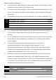
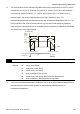

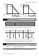

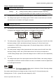
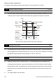
Table Of Contents
- Preface
- Table of Contents
- Chapter 1 Introduction
- Chapter 2 Installation and Wiring
- Chapter 3 Start Up
- Chapter 4 Digital Keypad Operation
- Chapter 5 Parameters
- 5.1 Summary of Parameter Settings
- Group 0 User Parameters
- Group 1 Basic Parameters
- Group 2 Operation Method Parameters
- Group 3 Output Function Parameters
- Group 4 Input Function Parameters
- Group 5 Multi-Step Speed and PLC Parameters
- Group 6 Protection Parameters
- Group 7 Motor Parameters
- Group 8 Special Parameters
- Group 9 Communication Parameters
- Group A PID Parameters
- 5.2 Parameter Settings for Applications
- 5.3 Description of Parameter Settings
- Group 0: User Parameters
- Group 1: Basic Parameters
- Group 2: Operation Method Parameters
- Group 3: Output Function Parameters
- Group 4: Input Function Parameters
- Group 5: Multi-step Speeds and PLC (Process Logic Control) Parameters
- Group 6: Protection Parameters
- Group 7: Motor Parameters
- Group 8: Special Parameters
- Group 9: Communication Parameters
- Group A: PID Control
- 5.1 Summary of Parameter Settings
- Chapter 6 Fault Code Information
- Chapter 7 Troubleshooting
- 7.1 Over Current (OC)
- 7.2 Ground Fault
- 7.3 Over Voltage (OV)
- 7.4 Low Voltage (Lv)
- 7.5 Over Heat (OH)
- 7.6 Overload
- 7.7 Keypad Display is Abnormal
- 7.8 Phase Loss (PHL)
- 7.9 Motor cannot Run
- 7.10 Motor Speed cannot be Changed
- 7.11 Motor Stalls during Acceleration
- 7.12 The Motor does not Run as Expected
- 7.13 Electromagnetic/Induction Noise
- 7.14 Environmental Condition
- 7.15 Affecting Other Machines
- Chapter 8 Maintenance and Inspections
- Appendix A Specifications
- Appendix B Accessories
- Appendix C How to Select the Right AC Motor Drive
Chapter 5 Parameters|VFD-S Series
5-32 Revision August 2008, SE09, SW V2.61
For example: When using the meter with full scale of 5 volts, adjust Pr.3-01 to 50%.
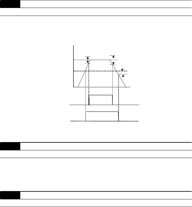
3-02 Desired Frequency Attained Unit: 0.1
Settings d1.0 to d400 Hz Factory Setting: d1.0
If a multi-function output terminal is set to function as Desired Frequency Attained (Pr.3-05 or
3-06=d9), then the output will be activated when the programmed frequency is attained.
Desired Freq.
Detection
range
-2Hz
Detection range
+
-
4Hz
Detection range
+
-
2Hz
Time
Freq.
Max. Output
Freq.
Pr.3-02
ON
ON
OFF
OFF
OFF
OFF
Preset Freq.
Attained
indication
Pr.3-05 to 3-06
Desired Freq.
Attained
Indication
Pr.3-05 to 3-06
Desired Freq. Attained & Preset Freq. Attained
3-03 Terminal Count Value Unit: 1
Settings d0 to d999 Factory Setting: d0
The parameter determines the upper limit value of the internal counter. The internal counter
can be triggered by the external terminal (Pr.4-4 to Pr.4-8, d19). Upon completion of counting,
the specified output terminal will be activated. (Pr.3-05, Pr.3-06, d14).
3-04 Preliminary Count Value Unit: 1
Settings d0 to d999 Factory Setting: d0
When the counter value is counted up from “1” to the setting value of this parameter, the
corresponding multi-function output terminal which set to d15 as Preliminary Counter Value
Attained will be closed. The application can be that closing the multi-function output terminal
makes the AC drive operate at low speed until stop before the counting value is going to be
attained.
The timing diagram is shown below: