
Network Device Product Manual


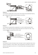
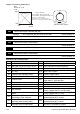
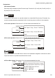

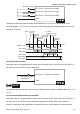
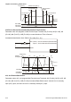
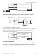
Table Of Contents
- Preface
- Table of Contents
- Chapter 1 Introduction
- Chapter 2 Installation and Wiring
- Chapter 3 Start Up
- Chapter 4 Digital Keypad Operation
- Chapter 5 Parameters
- 5.1 Summary of Parameter Settings
- Group 0 User Parameters
- Group 1 Basic Parameters
- Group 2 Operation Method Parameters
- Group 3 Output Function Parameters
- Group 4 Input Function Parameters
- Group 5 Multi-Step Speed and PLC Parameters
- Group 6 Protection Parameters
- Group 7 Motor Parameters
- Group 8 Special Parameters
- Group 9 Communication Parameters
- Group A PID Parameters
- 5.2 Parameter Settings for Applications
- 5.3 Description of Parameter Settings
- Group 0: User Parameters
- Group 1: Basic Parameters
- Group 2: Operation Method Parameters
- Group 3: Output Function Parameters
- Group 4: Input Function Parameters
- Group 5: Multi-step Speeds and PLC (Process Logic Control) Parameters
- Group 6: Protection Parameters
- Group 7: Motor Parameters
- Group 8: Special Parameters
- Group 9: Communication Parameters
- Group A: PID Control
- 5.1 Summary of Parameter Settings
- Chapter 6 Fault Code Information
- Chapter 7 Troubleshooting
- 7.1 Over Current (OC)
- 7.2 Ground Fault
- 7.3 Over Voltage (OV)
- 7.4 Low Voltage (Lv)
- 7.5 Over Heat (OH)
- 7.6 Overload
- 7.7 Keypad Display is Abnormal
- 7.8 Phase Loss (PHL)
- 7.9 Motor cannot Run
- 7.10 Motor Speed cannot be Changed
- 7.11 Motor Stalls during Acceleration
- 7.12 The Motor does not Run as Expected
- 7.13 Electromagnetic/Induction Noise
- 7.14 Environmental Condition
- 7.15 Affecting Other Machines
- Chapter 8 Maintenance and Inspections
- Appendix A Specifications
- Appendix B Accessories
- Appendix C How to Select the Right AC Motor Drive
Chapter 5 Parameters|VFD-S Series
Revision August 2008, SE09, SW V2.61 5-37
Example 6:
In this example, a negative bias is used to provide a noise margin. Also a potentiometer frequency
gain is used to allow the Maximum Output Frequency to be reached.
Hz
0V
10V
27
0
54
Potentiometer Scale
Max.
Output
Freq.
60Hz
Pr.1-00
0Hz
0V
10V
Factory Settings
Pr.1-00=60Hz--Max. output Freq.
Pr.4-00=10%--Potentiometer bias freq.
Pr.4-01=1 -- Bias polarity
Pr.4-02=111% -- Pot. freq. gain
Pr.4-03=0 -- Forward motion only
Negative
bias 6H
z
1V
It's 0Hz
within
this
range.
Gain adjustment
Calculation of gain
Pr.4-02=(
10V
9V
)X100%=111%
Example 7:
In this example, the potentiometer is programmed to run a motor is both forward and reverse
direction. A motor will be idle when the potentiometer position is at mid-point of its scale. Using
Pr.4-03 will disable the external FWD and REV controls.
Hz
0V
10V
0
60
Potentiometer Scale
Max.
Output
Freq.
Pr.1-00
Factory Settings
Pr.1-00=60Hz--Max. output Freq.
Pr.4-00=30Hz--Potentiometer bias freq.
Pr.4-01=1 -- bias polarity
Pr.4-02=200% -- pot. freq. gain
Pr.4-03=1 -- pot. REV motion enable
60Hz
30Hz
0Hz
0V
5V
10V
30Hz
60Hz
REV
FWD
REV.
FWD.
60
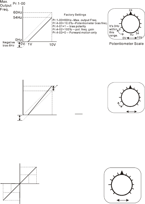
Example 8:
In this example, the option of anti-slope is shown. Anti-slope is used in an application where control
of pressure, temperature, or flow is needed. Under a high pressure or flow situation, a sensor will
generate a large signal such as 20 mA or 10V. With anti-slope enable, the large signal will slow or
stop the AC drive.