
Network Device Product Manual


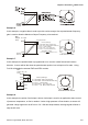

Table Of Contents
- Preface
- Table of Contents
- Chapter 1 Introduction
- Chapter 2 Installation and Wiring
- Chapter 3 Start Up
- Chapter 4 Digital Keypad Operation
- Chapter 5 Parameters
- 5.1 Summary of Parameter Settings
- Group 0 User Parameters
- Group 1 Basic Parameters
- Group 2 Operation Method Parameters
- Group 3 Output Function Parameters
- Group 4 Input Function Parameters
- Group 5 Multi-Step Speed and PLC Parameters
- Group 6 Protection Parameters
- Group 7 Motor Parameters
- Group 8 Special Parameters
- Group 9 Communication Parameters
- Group A PID Parameters
- 5.2 Parameter Settings for Applications
- 5.3 Description of Parameter Settings
- Group 0: User Parameters
- Group 1: Basic Parameters
- Group 2: Operation Method Parameters
- Group 3: Output Function Parameters
- Group 4: Input Function Parameters
- Group 5: Multi-step Speeds and PLC (Process Logic Control) Parameters
- Group 6: Protection Parameters
- Group 7: Motor Parameters
- Group 8: Special Parameters
- Group 9: Communication Parameters
- Group A: PID Control
- 5.1 Summary of Parameter Settings
- Chapter 6 Fault Code Information
- Chapter 7 Troubleshooting
- 7.1 Over Current (OC)
- 7.2 Ground Fault
- 7.3 Over Voltage (OV)
- 7.4 Low Voltage (Lv)
- 7.5 Over Heat (OH)
- 7.6 Overload
- 7.7 Keypad Display is Abnormal
- 7.8 Phase Loss (PHL)
- 7.9 Motor cannot Run
- 7.10 Motor Speed cannot be Changed
- 7.11 Motor Stalls during Acceleration
- 7.12 The Motor does not Run as Expected
- 7.13 Electromagnetic/Induction Noise
- 7.14 Environmental Condition
- 7.15 Affecting Other Machines
- Chapter 8 Maintenance and Inspections
- Appendix A Specifications
- Appendix B Accessories
- Appendix C How to Select the Right AC Motor Drive
Chapter 5 Parameters|VFD-S Series
Revision August 2008, SE09, SW V2.61 5-39
Explanations:
d0 Parameter Disable:
Enter value (d0) to disable any Multi-Function Input Terminal: M1 (Pr.4-04), M2 (Pr.4-05), M3 (Pr.4-
06), M4 (Pr.4-07) or M5 (Pr.4-08).
NOTE
The purpose of this function is to provide isolation for unused Multi-Function Input Terminals. Any
unused terminals should be programmed to d0 to insure they have no effect on drive operation.
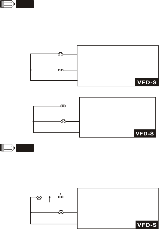
d1 Two wire operation: Restricted to Pr.4-04 and external terminals M0, M1.
FWD/STOP
REV/STOP
M0 "Open": Stop, "Close": FWD Run
M1 "Open": Stop, "Close":REV Run
GND
d2 Two wire operation: Restrict to Pr. 4-04 and external terminals M0, M1.
RUN/STOP
REV/FWD
M0 "Open": Stop, "Close": Run
M1 "Open": FWD, "Close":REV
GND
NOTE
Multi-function Input Terminal M0 does not have its own parameter designation. M0 must be used in
conjunction with M1 to operate two and three wire control.
d3 Three Wire Control: Restricted to Pr.4-04 control terminals M0, M1, M2.
STOP RUN
REV/FWD
M0 Run command, Runs when "close"
M2 Stop command, stops when "Open"
M1 REV/FWD Run selection
"Open": FWD Run
"Close": REV Run
GND