
Digital I/O Extension Unit Instruction Manual

http://www.delta.com.tw/industrialautomation/
5011658300-MNE0
2007-01-23
Digital I/O Extension Unit
(Pin Headed)
Instruction Sheet
Warning
3 Please read this instruction sheet carefully before use.
3
DVP-Slim is an OPEN-TYPE device and therefore should be installed in an enclosure free of airborne dust, humidity,
electri shock and vibration. The enclosure should prevent non-maintenance staff from operating the device (e.g. key or
specific tools are required to open the enclosure) in case danger and damage on the device may occur.
3 DO NOT connect input AC power supply to any of the I/O terminals; otherwise serious damage may occur. Check all the
wiring again before switching on the power. DO NOT touch any terminal when the power is switched on.
X Introduction
1.1 Model Explanation & Peripherals
Thank you for choosing Delta DVP-Slim series programmable logic controller. DVP-Slim series pin-headed digital I/O
extension unit offers 32 points. For DVP-SS/SA/SX/SC series MPU, the maximum digital I/O extension points (including
the MPU) can reach 128 points. For SV series MPU, the maximum digial I/O extension points (including the MPU) can
reach 256 points. In addition, maximum 8 additional special modules (AD/DA/PT/TC/XA/PU) can be extended to
DVP-Slim series extension unit.
Nameplate Explanation
VX.XXAX
24Vdc 1W
0.1A(24VDC)POINT
MADE IN XXXXX
32SN11TNT7020001
Delta PLC model name
Power input spec.
Output point module spec.
Barcode & serial No.
Version
Model Name
Serial No.
Input point extension unit
Output point extension unit
M:
N:
DVP series
Points (32 for output)
Module type
TN:
N:
NPN transistor
No output module
DC power input
Production No.
Model name
Production week
Production year (2007)
Production plant
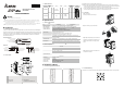
1.2 Product Profile
Unit: mm
c
POWER, L.V (low voltage) indicator
h
Extension unit positioning hole
d
Model name
i
Nameplate
e
Extension unit fixing clip
j
Extension unit fixing clip
f
I/O terminals
k
DIN rail (35mm)
g
DIN rail clip
l
Connection port for extension unit
1.3 Model Information
Input Output
Model name
Power
supply
Points
Type Points
Type
Dimension
(mm)
Outline
DVP32SM11N
32
DC Type
Sink/Source
0 N/A
DVP32SN11TN
24V DC
0 N/A 32
(NPN)
Transistor
25.2
90
60
Y Specifications
2.1 Electrical Specifications
Model
Item
DVP32SM11N DVP32SN11TN
Power supply voltage 24V DC (-15% ~ 20%) (with DC input polarity reverse protection)
Motion specification Within 5ms of the momentary power loss, the device will keep on operating.
Power consumption 1W 1.5W
Insulation resistance >5 MΩ (all I/O point-to-ground: 500V DC)
Noise immunity
ESD (IEC 61131-2, IEC 61000-4-2): 8KV Air Discharge
EFT (IEC 61131-2, IEC 61000-4-4): Power Line: 2KV, Digital I/O: 1KV,
Analog & Communication I/O: 1KV
Damped-Oscillatory Wave: Power Line: 1KV, Digital I/O: 1KV
RS (IEC 61131-2, IEC 61000-4-3): 26MHz ~ 1GHz, 10V/m
Earth
The diameter of grounding wire shall not be less than that of L, N terminal of the
power. (When many PLCs are in use at the same time, please make sure every PLC
is properly grounded.)
Operation/storage
environment
Operation: 0ºC ~ 55ºC (temperature); 50 ~ 95% (humidity); pollution degree 2
Storage: -40ºC ~ 70ºC (temperature); 5 ~ 95% (humidity)
Shock/vibration
immunity
International standards: IEC1131-2, IEC 68-2-6 (TEST Fc)/IEC1131-2 & IEC 68-2-27
(TEST Ea)
Weight (g) 70g 70g
2.2 I/O Point Specifications
Input Point
Input type DC (SINK or SOURCE)
Input current 24VDC, 5mA
Active level
Off Æ On more than 16V DC
On Æ Off less than 14.4V DC
Response time Approx. 10ms, 0 ~ 15ms adjustable from D1020, D1021
Circuit isolation /
operation instruction
By photocoupler / LED On
Output Point
Output type Transistor – T (NPN)
Current specification 0.1A/point
Voltage specification 5 ~ 24 VDC
Maximum load 55ºC/1A (COM), 25ºC/2.4A (COM)
Response time
Off Æ On less than 0.1ms
On Æ Off less than 0.3ms
Z Installation & Wiring
3.1 Terminals of Digital I/O Extension Unit
DVP32SM11N DVP32SN11TN
21 22
23
24
25
26
27
28
29
30
31
32
33
34
35
36
37
38
39
40
1
2
3
4
5
6
7
8
9
10
11
12
13
14
15
16
17
18
19
20
X21
X23
X25
X27
X31
X33
X35
X37
S/S
NC
X1
X3
X5
X7
X11
X13
X15
X17
S/S
NC
X20
X22
X24
X26
X30
X32
X34
X36
S/S
NC
X0
X2
X4
X6
X10
X12
X14
X16
S/S
NC
DVP32SM
21 22
23
24
25
26
27
28
29
30
31
32
33
34
35
36
37
38
39
40
1
2
3
4
5
6
7
8
9
10
11
12
13
14
15
16
17
18
19
20
Y21
Y23
Y25
Y27
Y31
Y33
Y35
Y37
GND
+24V
Y1
Y3
Y5
Y7
Y11
Y13
Y15
Y17
GND
+24V
Y20
Y22
Y24
Y26
Y30
Y32
Y34
Y36
GND
+24V
Y0
Y2
Y4
Y6
Y10
Y12
Y14
Y16
GND
+24V
DVP32SN
DVP32SN currently only offers TN (NPN) transistor output.
Please be aware of the following PIN wiring methods for DVP32SN to prevent burn-down of the extension unit.
1. PIN19, PIN20, PIN39 and PIN40 can only connected to +24V DC. The 4 points have already been designed as
short-circuit within the extension unit; therefore only 1 of the points needs to be wired.
2. PIN17, PIN18, PIN37 and PIN38 can only connected to GND. The 4 points have already been designed as
short-circuit within the extension unit; therefore only 1 of the points needs to be wired.
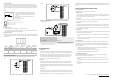
3.2 Connection
Step 1: Screw open t
he side cover of the extension
unit and you will see the connection port.
Step 2: Lift the fixing clip by the screwdriver.
Step 3: Adjust the positioning hole of the MPU and
the extension unit and meet the connection port on
the MPU with the extension unit to tightly connect
the two.
Step 4: Fasten the fixing clip on the extension unit
to complete the connection.
3.3 Installation & Wiring
Install the PLC in an enclosure with sufficient space around it to allow heat dissipation as shown in the figure below.
DVP
MPU
D
D
DD
D > 50mm