RTU-DNET DeviceNet Remote I/O Communication Module Application Manual
DeviceNet Remote I/O Communication Module RTU-DNET Warning 3 Please read this instruction carefully before use and follow this instruction to operate the device in order to prevent damages on the device or injuries to staff. 3 Switch off the power before wiring. 3 RTU-DNET is an OPEN TYPE device and therefore should be installed in an enclosure free of airborne dust, humidity, electric shock and vibration. The enclosure should prevent non-maintenance staff from operating the device (e.g.
DeviceNet Remote I/O Communication Module RTU-DNET 5 6 2 4.3 DeviceNet I/O Mapping Data .................................................................................................... 14 4.4 Example.................................................................................................................................... 17 HOW TO CONSTRUCT A DEVICENET NETWORK USING RTU-DNET ........................................... 22 5.1 How to Construct DeviceNet by RTU-DNET ......................
DeviceNet Remote I/O Communication Module RTU-DNET 1 Introduction 1. To ensure correct installation and operation of RTU-DNET, please read this chapter carefully before using your RTU-DNET. 2. This chapter only provides introductory information on RTU-DNET. For more detailed information on DeviceNet protocol, please refer to relevant references or literatures. 3. RTU-DNET is a remote I/O communication module applicable to the connection between DeviceNet and DVP Slim DIDO module and special modules.
DeviceNet Remote I/O Communication Module RTU-DNET Baud rates 125 kbps; 250 kbps; 500 kbps Electrical specification Voltage 11 ~ 25 VDC, supplied by internal bus from PLC MPU Current 28mA (typical), 125mA impulse current (24 VDC) Environment Noise immunity ESD (IEC 61131-2, IEC 61000-4-2): 8KV Air Discharge EFT (IEC 61131-2, IEC 61000-4-4): Power Line: 2KV, Digital I/O: 1KV Analog & Communication I/O: 1KV Damped-Oscillatory Wave: Power Line: 1KV, Digital I/O: 1KV RS (IEC 61131-2, IEC 61000-4-3)
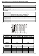
DeviceNet Remote I/O Communication Module RTU-DNET Special module (model name) Default I/O mapping data (DeviceNet → RTU-DNET) I/O mapping data (RTU-DNET → DeviceNet) Start CR Start CR Length (words) Length (words) DVP-04TC N/A N/A CR#14 4 DVP-04PT N/A N/A CR#18 4 DVP-06XA CR#10 2 CR#12 4 DVP-01PU CR#42 4 CR#33 4 Note: While connected to a special module, the start CR and length of upload/download data of RTU-DNET can be set up in DeviceNet network configuration tool.
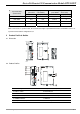
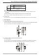
DeviceNet Remote I/O Communication Module RTU-DNET 2.3 DeviceNet Connection Port The connector is used on the connection to DeviceNet. Wire by using the connector enclosed with RTU-DNET. PIN Signal Color Content 1 V- Black 0 VDC 2 CAN_L Blue Signal- 3 SHIELD - Shielded 4 CAN_H White Signal+ 5 V+ Red 24 VDC 5 4 3 2 1 2.4 RUN/STOP Switch RUN/STOP action Explanation STOP → RUN 1. Re-detecting the extension module. 2. Reading/writing the data in the extension module.
DeviceNet Remote I/O Communication Module RTU-DNET OFF When DeviceNet is off, the I/O data in the buffer area will be cleared. ON When DeviceNet is off, the I/O data in the buffer area will be held. IN0 IN1 Reserved Note: z Please set up the function switch when the power is switched off. After the setup is completed, re-power RTU-DNET. z When RTU-DNET is operating, changing the setting of the function switch will be invalid.
DeviceNet Remote I/O Communication Module RTU-DNET 3.3 Connecting to DeviceNet Connection Port z The colors on the PINs on the DeviceNet connection port match the colors of the connection cables. Make sure you connect the cable to the right PIN. z We recommend you also apply Delta’s power module in the connection. 4 How to Configure RTU-DNET In this section we will introduce how RTU-DNET as a DeviceNet slave realizes the data exchange between DeviceNet master and DVP Slim DI/DO extension unit.
DeviceNet Remote I/O Communication Module RTU-DNET No. Item Unit 5 Length of input data of special module Word The length of input data of the special module connected to RTU-DNET 6 Length of output data of special module Word The length of output data of the special module connected to RTU-DNET 7 Length of input I/O data Byte The sum of the length of the status word of RTU-DNET and the input data of the special module connected to it. One input channel of the special module occupies 2 bytes.
DeviceNet Remote I/O Communication Module RTU-DNET Byte position Data written into special module Data read from special module 1 R/R[0]+Service Code[0x10] R/R[0]+Service Code[0x0E] 2 Class ID [0x9C] Class ID [0x9C] 3 Instance ID Instance ID 4 Attribute ID Attribute ID 5 Low byte of Service Data N/A 6 High byte of Service Data N/A 7 N/A N/A Byte position Data written into special module Data read from special module 0 Frag[0]+XID+MAC ID Frag[0]+XID+MAC ID 1 R/R[1]+Service Code
DeviceNet Remote I/O Communication Module RTU-DNET Attribute ID Access rule Name Range Default 8 Get Status word 0~255 N/A Displaying the status of RTU-DNET. See 4.3 for more details. For setting up the mode of RTU-DNET, e.g. “H8000” for STOP mode and “H8001” for RUN mode. See 4.3 for more details. 9 Get/Set Control word N/A N/A 10 Get/Set Diagnostic interval time 1 ~ 65 secs 5 secs The interval when RTU-DNET executes diagnosis.
DeviceNet Remote I/O Communication Module RTU-DNET Attribute ID Access rule Name Range Default Explanation 1 Special module and configuration inconsistent 0 Configuration data valid 1 Configuration data invalid 0 Special module identifiable 1 Special module unidentifiable b3 b4 b5~b15 Work mode of special module 0: auto 1: custom 5 Get/Set Work mode 0~1 0 6 Get/Set Number of input data 0~8 N/A Number of input data of special modules connected 7 Get/Set Number of output data
DeviceNet Remote I/O Communication Module RTU-DNET Attribute ID Access rule 30 Get/Set 31 Name Range Default Start CR for module 6 input data N/A N/A Start CR for the input data of special module 6 Get/Set Input data length for module 6 N/A N/A Length of input data of special module 6 32 Get/Set Start CR for module 7 input data N/A N/A Start CR for the input data of special module 7 33 Get/Set Input data length for module 7 N/A N/A Length of input data of special module 7 34 Ge
DeviceNet Remote I/O Communication Module RTU-DNET Attribute ID Access rule 61 Get/Set 62 Name Range Default Explanation Output data length for module 6 N/A N/A Length of output data of special module 6 Get/Set Start CR for module 7 output data N/A N/A Start CR for the output data of special module 7 63 Get/Set Output data length for module 7 N/A N/A Length of output data of special module 7 64 Get/Set Start CR for module 8 output data N/A N/A Start CR for the output data of spe
DeviceNet Remote I/O Communication Module RTU-DNET bit Status value Explanation 2 0/1 Reserved 3 0/1 Reserved 4 0/1 Reserved 5 0/1 Reserved 6 0/1 Reserved 7 0/1 Reserved 8 0/1 Reserved 9 0/1 Reserved 10 0/1 Reserved 11 0/1 Reserved 12 0/1 Reserved 13 0/1 Reserved 14 0/1 Reserved 0 Disabling control word 1 Enabling control word Status value Explanation 15 Status word bit 0 RTU-DNET detects DI/DO extension unit.
DeviceNet Remote I/O Communication Module RTU-DNET bit Status value Explanation 14 0/1 Reserved 15 0/1 Reserved 2.
DeviceNet Remote I/O Communication Module RTU-DNET Master (byte) RTU-DNET … … z RTU-DNET → DeviceNet master Master (byte) RTU-DNET 0 Low byte of status word of RTU-DNET RTU-DNET 1 High byte of status word of RTU-DNET 2 Low byte of the 1st special module output channel 1 3 High byte of the 1st special module output channel 1 Special module 4 Low byte of the 1st special module output channel 2 5 High byte of the 1st special module output channel 2 … … N X0 ~ X7 of the 1st Slim DI/DO X0 ~
DeviceNet Remote I/O Communication Module RTU-DNET Item Content DIDO Input Points (X) 16 bits DIDO Output Points (Y) 8 bits AIAO Module Number 4 Input IO Data Length 26 bytes Output IO Data Length 5 bytes Software screen If the I/O data include control word and status word of RTU-DNET, the information of the extension module connected to RTU-DNET are as follows: Item Content DIDO Input Points (X) 16 bits DIDO Output Points (Y) 8 bits AIAO Module Number 4 Input IO Data Length 28 bytes
DeviceNet Remote I/O Communication Module RTU-DNET (2) Double click on RTU-DNET icon, and the “Node Configuration…” dialog box will appear. (3) Click on “IO Configure…” button in “Node Cnfiguration…” dialog box, and you will then see “RTU Configuration” page. (4) Click on “Scan IO”, and the “Warning” dialog box will appear.
DeviceNet Remote I/O Communication Module RTU-DNET (5) Click on “OK”. DeviceNetBuilder will then display the special module connected and the number of digital I/O points on the “RTU Configuration” page. (6) Double click on “04TC” icon, and you will then see the “AIAO Module Configuration” dialog box, as below. The content in Input Data >> Link 1 column is “CR14-Present temperature of CH1(C)”. (7) Set the Work Mode to “Custom” and Input Data >> Link 1 to “CR6-CH1 average degree(C)”.
DeviceNet Remote I/O Communication Module RTU-DNET (8) Click on “OK” in “AIAO Module Configuration” page and return to “RTU Configuration” page. (9) Click on “Dowload” to download the configuration to RTU-DNET. (10) After the download is completed, click on “OK”.
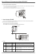
DeviceNet Remote I/O Communication Module RTU-DNET 5 How to Construct a DeviceNet Network Using RTU-DNET In this section, we will explain how to configure RTU-DNET and the I/O mapping relation between RTU-DNET and DVPDNET-SL by an application example. 5.1 How to Construct DeviceNet by RTU-DNET 1. The DeviceNet network DVPDNET-SL DVP28SV DVPDNET DVP28SV DeviceNet network configuration tool RUN STOP DVP-02DA DVP-04PT DVP-04TC DVP-04AD DVP-16SP DVP-08ST RT U- DN ET Master DeviceNet 2.
DeviceNet Remote I/O Communication Module RTU-DNET (2) Select “Setup” => “Communication Setting” => “System Channel”, and the “Serial Port Setting” dialog box will appear. (3) Set up the communication parameters in the PC and DVP-SV, e.g. the communication port, address, baud rate and communication format.
DeviceNet Remote I/O Communication Module RTU-DNET (6) Click on “OK”, and DeviceNetBuilder will start to scan the entire network. (7) If the bar on the dialog box does not progress, it means the connection between the PC and DVP-SVis abnormal, or there are other programs also usinig the COM port on the PC. After the scan is completed, the dialog box will tell you that the scan is completed, and the icons and device names of all the nodes scanned on the network will be shown on the screen.
DeviceNet Remote I/O Communication Module RTU-DNET (9) Click on “IO Configure…” button in “Node Configuration" dialog box, and you will then see “RTU Configuration” page. (10) Click on “Scan IO”, and the “Warning” dialog box will appear. (11) Click on “OK”. DeviceNetBuilder will then detect the special module connected to RTU-DNET and the number of points in the Slim DI/DO extension unit and display the information on “RTU Configuration” page.
DeviceNet Remote I/O Communication Module RTU-DNET (12) Double click on RTU-DNET icon, and you will then see “RTU Setup” dialog box. (13) Set up the parameters in RTU-DNET and confirm its I/O information. Item Input IO Data Length Output IO Data Length DIDO Input Points (X) DIDO Output Points (Y) AIAO Module Number Diagnostic Intervel Time IO Module Offine Treatment 26 Function Default The sum of the length of the status word of RTU-DNET and the input data of the special module connected to it.
DeviceNet Remote I/O Communication Module RTU-DNET Item Function IO Module Error Treatment How RTU-DNET will react when it detects errors. You can choose “Ignored”, “Alarm” or “Stop DeviceNet IO”. For you to decide whether to add control word and status word to I/O data. When you choose not to do it, the I/O data Add control word in RTU-DNET and DeviceNet master will not include control and status word to word and status word.
DeviceNet Remote I/O Communication Module RTU-DNET (3) Confirm all the settings and click on “OK”. Next, download the configuration to DVPDNET-SL. If DVP-SV is in RUN mode while you are downloading the configuration, a "Warning” dialog box will appear. (4) Click on “OK” to continue the download. Make sure DVP-SV is in RUN mode. Now, you can see the MS LED and NS LED on RTU-DNET become green. 3. Follow the steps given above to configure DeviceNet network.
DeviceNet Remote I/O Communication Module RTU-DNET (1) DVPDNET-SL → RTU-DNET Register in DVPDNET-SL Devices in extension module D6287H D6287L D6288H High byte of CH1 on DVP-02DA Special module D6288L D6289H Low byte of CH1 on DVP-02DA High byte of CH2 on DVP-02DA Low byte of CH2 on DVP-02DA Slim DI/DO Y0 ~ Y7 on DVP-16SP (2) RTU-DNET → DVPDNET-SL Register in DVPDNET-SL Devices in extension module D6037H High byte of CH1 on DVP-04AD D6037L Low byte of CH1 on DVP-04AD D6038H High byte of CH2 on
DeviceNet Remote I/O Communication Module RTU-DNET Register in DVPDNET-SL D6287H D6287L Devices in extension module RTU-DNET control word D6288H D6288L D6289H Low byte of control word in RTU-DNET High byte of CH1 on DVP-02DA Special module Low byte of CH1 on DVP-02DA High byte of CH2 on DVP-02DA Low byte of CH2 on DVP-02DA D6289L D6290H High byte of control word in RTU-DNET Slim DI/DO Y0 ~ Y7 on DVP-16SP (2) RTU-DNET → DVPDNET-SL Register in DVPDNET-SL D6037H D6037L RTU-DNET status word High byt
DeviceNet Remote I/O Communication Module RTU-DNET 6 LED Indicator & Trouble-shooting There are five LED indicators on RTU-DNET. POWER LED displays if the power of RTU-DNET is working normally. RUN LED displays the working status of RTU-DNET. ALRAM LED shows if RTU-DNET is operating normally. NS LED and MS LED display the communication connection status of RTU-DNET. 6.1 POWER LED LED status Off Green light on Indication How to correct Power is abnormal. Make sure RTU-DNET is powered.
DeviceNet Remote I/O Communication Module RTU-DNET LED status Red light on Indication voltage How to correct 2. Acquire diagnostic information through DeviceNetBuilder. Fatal error; errors in configuration data Acquire diagnostic information through DeviceNetBuilder. 6.
DeviceNet Remote I/O Communication Module RTU-DNET Common services Service code Implemented for Service name Class Instance 0x05 No Yes Reset 0x0E Yes Yes Get_Attribute_Single 0x10 No No Find_Next_Object_Instance Class 0x02 – Message router object Class attribute Attribute ID Access rule Name Data type 1 Get Revision UINT 6 Get MaxIdClass UINT 7 Get MaxIdInstance UINT Attribute ID Access rule Name Data type 2 Get NumAvailable UINT 3 Get NumActive UINT Instance
DeviceNet Remote I/O Communication Module RTU-DNET Service code Implemented for Service name Class Instance 0x10 No Yes Set_Attribute_Single 0x4B No Yes Allocate_Master/Slave_Connection_Set 0x4C No Yes Release_Master/Slave_Connection_Set Class 0x05 – Connection object Class attribute Attribute ID Access rule Name Data type 1 Get Revision UINT Instance 1: Explicit message connection Attribute ID Access rule Name Data type 1 Get State USINT 2 Get InstanceType USINT 3
DeviceNet Remote I/O Communication Module RTU-DNET Common services Service code Implemented for Service name Class Instance 0x05 No Yes Reset 0x0E Yes Yes Get_Attribute_Single 0x10 No Yes Set_Attribute_Single Appendix B: DeviceNet Objects Defined by RTU-DNET Class 0x9A – RTU-DNET setup parameter object Class attribute Attribute ID Access rule Name Data type 1 Get Revision UINT Instance 1 Attribute ID Access rule Name Range Default Explanation N/A The sum of the length of t
DeviceNet Remote I/O Communication Module RTU-DNET Attribute ID Access rule Name Range Default offline treatment Explanation 0: Ignored 1: Alarm 2: Stop DeviceNet IO 12 Get/Set Special module error treatment 0~2 1 How RTU-DNET will react when it detects errors. 0: Ignored 1: Alarm 2: Stop DeviceNet IO 13 Get/Set RTU-DNET configuration validation N/A 0 Validating the configuration of RTU-DNET when set to “11”. 14 Get/Set Reset RTU-DNET N/A 0 Resetting RTU-DENT when set to “10”.
DeviceNet Remote I/O Communication Module RTU-DNET Attribute Access rule ID Name Range Default Explanation 1 b5 ~ b15 Special module unidentifiable Reserved Work mode of special module 0: auto 1: custom 5 Get/Set Work mode 0~1 0 6 Get/Set Number of input data 0~8 N/A Number of input data of special modules connected 7 Get/Set 0~8 N/A Number of output data of special modules connected Number of output data 8 9 Reserved Get Error code N/A 10~19 Error code in special module Reserved
DeviceNet Remote I/O Communication Module RTU-DNET Attribute ID Access rule Name Range Default Explanation for module 1 52 Get/Set Start CR for module 2 output data N/A N/A Start CR for the output data of special module 2 53 Get/Set Output data length for module 2 N/A N/A Length of output data of special module 2 54 Get/Set Start CR for module 3 output data N/A N/A Start CR for the output data of special module 3 55 Get/Set Output data length for module 3 N/A N/A Length of outpu
DeviceNet Remote I/O Communication Module RTU-DNET Attribute ID Access rule Name Data type … … … UINT 9 Get/Set Content in CR#8 UINT 10 Get/Set Content in CR#9 UINT … … … UINT Common services Service code Implemented for Data type Claass Instance 0x0E Yes Yes Get_Attribute_Single 0x10 No Yes Set_Attribute_Single DVP-PLC Application Manual 39