Table of Contents TPEditor User Manual Chapter 1 TPEditor Operation ....................................................................................... 1-1 1-1 Recommended System Requirements ............................................................ 1-1 1-2 TPEditor Software Installation ......................................................................... 1-1 1-3 Basic Introduction ............................................................................................
Table of Contents MEMO ii © DELTA ELECTRONICS, INC.
1 TPEditor Operation Chapter 1 TPEditor Operation In this chapter, it introduces general functions of TPEditor in Windows. Detailed information for each function is discussed in the following sections.
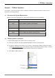
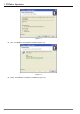
1 TPEditor Operation ■ Execute setup.exe saved in the specified directory (Figure 1-2). After pressing OK button, the system will setup automatically (Figure 1-3). Figure 1-2 Figure 1-3 ■ Then, the users will see the image in Figure 1-4. Click Next> for the next setup. Figure 1-4 ■ After pressing Next button, the system will ask the users to enter the Customer Information, i.e. User Name and Organization. After completing the customer information, click Next> for the next setup.
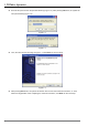
1 TPEditor Operation Figure 1-5 ■ After pressing Next button, the users will get the following tab to choose the destination location (Figure 1-6). To select the default directory C:\Program Files\Delta Industrial Automation\TPEditor 1.10\, click Next> for the next step, and the system will install TPEditor program in the default directory. To select a directory other than the default directory, please click Change.
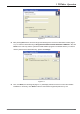
1 TPEditor Operation Figure 1-7 ■ Then, click Install to start TPEditor installation (Figure 1-8). Figure 1-8 ■ 1-4 Finally, click Finish to complete the installation (Figure 1-9). © DELTA ELECTRONICS, INC.
1 TPEditor Operation Figure 1-9 ■ After setup, TPEditor program will be installed in the specified directory. The users can start TPEditor by double-clicking the icon of TPEditor shortcut on the desk, or from Windows taskbar, click Start > Programs > Delta Industrial Automation > PLC > TPEditor > TPEditor x.xx (x.xx indicates the version of TPEditor (Figure 1-10). Figure 1-10 ■ © The start-up display of TPEditor is shown as the following Figure 1-11. DELTA ELECTRONICS, INC.
1 TPEditor Operation Figure 1-11 1-3 Basic Introduction TPEditor software is the user-friendly program editor of TP series terminal panels for Windows. The users can see the design result on the screen immediately, motivated by the concept of “What You See is What You Get” that TPEditor adopts. The screen on TPEditor is the same as the actual screen of TP series. TPEditor uses object-oriented programming design.
1 TPEditor Operation Mouse Cursor 1-5 Name Function Arrow Cursor Display where the mouse is (display the current position of the mouse). 、 Resize Cursor Display when adjusting the size of the window or the object. ¨ Cross Cursor Display when creating a new object or when drawing a picture. I ” I “ Cursor Display when editing the text. Characters and Chinese language can be entered when this “ I ” cursor appears.
1 TPEditor Operation ■ Object Toolbar The users can click the icons on Object Toolbar to create an object on the screen directly. For the users that do not familiar with the operation of the computer, this Toolbar provides the users a fast way to work in TPEditor more easily. ■ Geometric Toolbar This Toolbar provides an easy access to draw many kinds of geometric drawings and perform editing on the screen very quickly just by clicking the mouse.
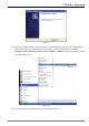
1 TPEditor Operation Figure 1-13 After clicking or selecting File (F) > New, the New Project tab will display (Figure 1-14). Enter the Set Device Type, TP Type and File Name. Click OK button, and a new editing screen will be opened in TPEditor. Regarding the pull-down options of the Menu Bar, their functions will be introduced in the following sections. Figure 1-14 © DELTA ELECTRONICS, INC.
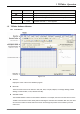
1 TPEditor Operation 1-5-2 Menu Bar File The pull-down options of File function are described as follows (Figure 1-15): Figure 1-15 ■ New: Create a new file (project). ■ Open File: Open an old file (project). ■ Save: Save the current edited file (project). ■ Save as: Save the current edited file (project) to another file name. ■ Print: Print the current edited file (project) and set the printer.
1 TPEditor Operation ■ Add a New Page: Add a new edited screen of TPEditor. ■ Save Page Bitmap: Save the current edited screen to Clipboard or as a file. ■ Undo: Undo an action. ■ Redo: Redo an action. ■ Delete: Delete the selected objects on the screen. ■ Cut: Cut the selected objects on the screen. ■ Copy: Copy the selected objects on the screen. ■ Paste: Paste the objects that the users copy or cut. ■ Multi-Copy: Copy the selected objects to many ones in order.
1 TPEditor Operation Compile The pull-down options of Compile function are described as follows (Figure 1-18): Figure 1-18 ■ Build All: Compile all edited screen. Objects The pull-down options of Objects function are described as follows (Figure 1-19): Figure 1-19 ■ Static Text: It is used to type and edit words to show on the screen of TP series.
1 TPEditor Operation ■ Meter: After TP series reads the value of the corresponding PLC register, the users can use this object to convert the read value to a meter and display on the screen of TP series. ■ Message Display: After TP series reads the corresponding PLC contacts (ON or OFF) or the value of PLC register, using this object can automatically display the edited message text for each corresponding state on the screen of TP series directly.
1 TPEditor Operation ■ Page Manager: Preview and manage the edited screen. ■ TP Page: Display the edited TP screen. When the users work in the screen of Boot Page, clicking this command is to return to the edited TP screen. ■ Boot Page: Display the screen of Boot Page (start-up display).
1 TPEditor Operation Local Page Settings The pull-down options of Local Page Settings function are described as follows (Figure 1-22): Figure 1-22 ■ Page Jump Condition Setting: The users can enter page jump conditions in Page Jump Condition Setting tab. When the conditions are satisfied, the system will jump to the destination page (screen). ■ Function Key Setting: Clicking this option can open Function Key Setting tab and the users can define the button type and the function of all function keys.
1 TPEditor Operation Figure 1-23 Global Settings The pull-down options of Global Settings function are described as follows (Figure 1-24): Figure 1-24 ■ System Parameter Setting: After this option is clicked, Parameter Setting tab will appear and allow the users to enable the function of Page jump automatically/Backlight control, and Read & Write Block Setting. this option is enabled, after the PLC When address, TP address and Length are all set, the system will read the data from the TP register.
1 TPEditor Operation ■ System Function Key Setting: The users can use this option to define the button type and function of the function key. It is not necessary to set the function key in each page. But, once the function key is used in the page, the function key will function according to the definition of button type and defined function. (If the function settings of system conflict with the function settings set in each page, the function settings of each page get high priority.
1 TPEditor Operation ■ Communication Settings: Set the communication settings when connecting PC and TP series. ■ TP Protocol Setting: Set the communication settings between TP and monitored equipment, including the settings of RS-232 (COM1) and RS-485/RS-422 (COM2). ■ TP Object Communication Default Setting: Set the communication port and PLC ID number of all objects for connected equipment. ■ Change Device Type: Change the type and the devices of the connected controller.
1 TPEditor Operation ■ About: Display the software version of TPEditor and the related information. ■ TPEditor User Manual: Provide the user manual of TPEditor. Above is the basic introduction of TPEditor. Regarding the functions used frequently, please refer to the following sections for more detailed introduction. 1-6 TPEditor Software Detailed Introduction 1-6-1 File ■ New It is used to create a new file (project) in TPEditor. Do one of the followings: Method 1: Step 1.
1 TPEditor Operation Step 5: The default extension name of TPEdit program is .tpe. TPEdit will name the new project to be Tpe0. (The system will examine if the name of Tpe0.tpe exists or not. If Tpe0.tpe exists, the system will create a new project named as Tpe1. tpe, and vise versa.) The following Figure 1-30 is the window after a new project is created. Figure 1-30 Method 2: Click the icon on the toolbar. Method 3: Use keyboard shortcuts by pressing keys (Ctrl) + (N) to create a new project.
1 TPEditor Operation Step 2. After selecting File (F) > Open File, to create an old project, the Open dialog box will display (Figure 132) to let the users select the desired old file. Figure 1-32 File name Ö Enter or select the file name that the users want to open. Only the files matching the type in the “Files of Type” are shown and can be selected. Files of type Ö Select the types of the files that the users want to open. For example, Tpe File (*.tpe).
1 TPEditor Operation Figure 1-34 Step 2. The users can use their own language to edit the words on the screen. However, because it is the user menu, the font size could not be modified. Only the language can be changed. Step 3. Choose the screen that the users want to modify. Double-click the desired item, the Static Text Setting tab will appear to let the users change the language (Figure 1-35, Figure 1-36, Figure 1-37). Figure 1-35 1-22 © DELTA ELECTRONICS, INC.
1 TPEditor Operation Figure 1-36 Figure 1-37 Step 4. After editing is completed, in the system main menu of TP04G, choose “1.D/L AP PC TP04G”. Then, the words of “WAIT COMM……” will display on the screen of TP04G. Step 5. Back to TPEditor software program, click Communication(M) > Write Menu to TP(M). Usually, the functions of Write Menu to TP(M) are disabled and can not be used. It is available only when editing the user-defined Menu.
1 TPEditor Operation Figure 1-39 Step 2. Select the desired page (Figure 1-40). Figure 1-40 Step 3. Select the file type, text file (*.txt) or Excel file (*.xls) (Figure 1-41). 1-24 © DELTA ELECTRONICS, INC.
1 TPEditor Operation Figure 1-41 ■ Save In TPEditor, using this command is to save the current project. Do one of the followings: Method 1: Click File (F) > Save (Figure 1-42). Method 2: Click the icon on the toolbar. Method 3: Use keyboard shortcuts by pressing keys (Ctrl) + (S). Figure 1-42 ■ Save as In TPEditor, using this command is to save the current project to another file name.
1 TPEditor Operation Figure 1-43 Step 2. Enter a new file name and press Save button (Figure 1-44). Figure 1-44 ■ Print It is used to print the current edited file (project) and set the printer when it is completed. Do the followings: Step 1. Click File (F) > Print (Figure 1-45). Choose Print TP Page or Print Boot Page. 1-26 © DELTA ELECTRONICS, INC.
1 TPEditor Operation Figure 1-45 Step 2. Then, the following Printer tab will show up (Figure 1-46). The user can choose the way to print, Print by Page or Print by Picture, and select the data needed to be printed out. Clicking Printer Setup button is to set the connected printer. Figure 1-46 Step 3. Click Preview button to show the page as it would look if printed (Figure 1-47, Figure 1-48). © DELTA ELECTRONICS, INC.
1 TPEditor Operation Figure 1-47 Figure 1-48 1-28 © DELTA ELECTRONICS, INC.
1 TPEditor Operation ■ Close This command is used to close the current edited file (project). Click File (F) > Close, and the current edited project will be closed. ■ Exit This command is used to exit TPEditor. To exit TPEditor, click File (F) > Exit, or click the icon at the right upper corner of the window. Before using this command, ensure that the file is already saved, or it does not need to be saved before exiting TPeditor.
1 TPEditor Operation ■ Paste: Paste the objects that the users copy or cut. ■ Multi-Copy: Copy the selected objects to many ones in order. ■ Copy Page: Copy all the objects on the screen. ■ Paste Page: Paste all the objects that the users copy. ■ Move Up: When one object is on the top of another, move up the selected object. ■ Move Down: When one object is in the back of another, move down the selected object.
1 TPEditor Operation Figure 1-51 1-6-3 Compile Compile all edited application programs. Choose Compile (C) > Build All(A) or click the icon to compile application program to transmit to TP04G. After compiling successfully, the following dialog box will appear (Figure 1-52, Figure 1-53). Figure 1-52 Figure 1-53 1-6-4 Function Explanation of Objects The users can click Object(O) command from the menu bar (or use keyboard shortcuts by pressing keys (Ctrl) + (O)) to select the desired objects.
1 TPEditor Operation ■ Static Text Step 1. Choose Object(O) > Static Text(T) command from the menu bar or click the icon on the toolbar (Figure 1-54). At the moment, move the mouse on the editing screen area, the cursor will be a +. Left click and drag the mouse in the editing screen area. The screen will look like the Figure 1-55 below after the static text square is made.
1 TPEditor Operation Figure 1-55 Step 2. Move the mouse to static text square and then double left-click the mouse. Then, the following Static Text Setting tab will appear (Figure 1-56). Figure 1-56 Step 3. In Static Text Setting tab (Figure 1-56), the users can enter the text and set the font attributes (including Frame Setting, Text Direction, Alignment and Font setting these options). Frame Setting could be No Frame, Single Frame, Double Frame, Thick Frame, Dotted Line Frame or Dot Frame (Figure 1-57).
1 TPEditor Operation Figure 1-58 Figure 1-57 Figure 1-59 Figure 1-60 Figure 1-61 Step 4. After complete Static Text settings, the users can get the screen like Figure 1-62 below. If the text could not be displayed completely, the users could enlarge the size of text square. Click View(V) > Object Inspector command from the menu bar , a Property tab will show up on the screen and display all the properties of the static text object.
1 TPEditor Operation Figure 1-62 ■ Numeric/ASCII Display Step 1. Choose Object(O) > Numeric/ASCII Display(A) command from the menu bar or click the icon on the toolbar to create a Numeric/ASCII Display object. After double-clicking the object, the following Numeric/ASCII Display Setting tab will display (Figure 1-63). Figure 1-63 Step 2. After entering the device name and clicking © DELTA ELECTRONICS, INC. ALL RIGHTS RESERVED , the Refer Device tab like Figure1-64 will open.
1 TPEditor Operation Figure 1-64 Step 3. It is used to set write-in PLC Device Name, i.e. T, C, D or the Device Name, i.e. @V of TP05/08. The Device Number is shown in decimal format and the users could click to select the necessary Device Name. If the connected controller is AC motor drive (Inverter), it does not need to check the Device Name. The symbol $ will show after the Device Name to represent the absolute address of AC motor drive.
1 TPEditor Operation Step 9. After complete the settings, the users can get the screen like Figure 1-65 below. Step 10. Click View(V) > Object Inspector command from the menu bar, a Property tab will show up on the screen and display all the properties of the Numeric/ASCII Display object. The users also could change the settings of the Numeric/ASCII Display object directly by using the drop-down lists in Property tab.
1 TPEditor Operation Word Lamp: Choose Object(O) > Lamp(16x16)(L) > Word Lamp(W) command from the menu bar or click the icon on the toolbar to create a Word Lamp object. Step 1. After click Object(O) > Lamp(16x16)(L) > Word Lamp(W) command from the menu bar or click the icon on the toolbar, the users could create a Word Lamp object on the screen. Then, double-click the object, and the users can get the following Word Lamp Setting tab (Figure 1-67).
1 TPEditor Operation Current State 0 should be the greater than the setting range value of Current State 1, the setting range value of Current State 1 should be the greater than the setting range value of Current State 2, and vise versa. Step 4. When the users double click the field of “Device Value >= Range Value” by using the mouse, the following All States Table tab shown in Figure 1-69 will open for the users to set the setting range values of all states. Figure 1-69 Step 5.
1 TPEditor Operation Step 2. Double-click the square by using the mouse, a Open dialog box will appear to let the users select the desired display picture (the picture must be a BMP file). After selecting the desired BMP file and press Open(O) button, the screen will look like the following Figure 1-71. Figure 1-71 Step 3. Click View(V) > Object Inspector command from the menu bar, a Property tab will show up on the screen and display all the properties of the Static Bitmap object.
1 TPEditor Operation Figure 1-73 Figure 1-74 Dynamic Bitmap: Choose Object(O) > Bitmap(B) > Dynamic Bitmap(D) command from the menu bar or click the icon on the toolbar to import a Dynamic Bitmap file. Using this dynamic object can read the value of PLC register, perform the value comparison and display the result through the preset picture on the screen of TP series directly.
1 TPEditor Operation Step 2. Double-click the square by using the mouse, a Dynamic Bitmap Setting tab will appear to let the users select the Refer Device as Bit or Value (Figure 1-75). Figure 1-75 Figure 1-76 Step 3. When the Refer Device is set to Value, the Display Sequence could be either “From Max to Min” or “From Min to Max” (Figure 1-76). Step 4. The Dynamic Bitmap Setting tab is similar to Word Lamp Setting tab.
1 TPEditor Operation on the screen. Please note that if the Device Value is smaller than 100, no picture will display as the users do not specify its Current State and display picture.
1 TPEditor Operation ■ Scale Step 1. Choose Object(O) > Scale(S) command from the menu bar or click the icon on the Toolbar. Then, move the mouse on the editing screen area, the cursor will be a +. Left click and drag the mouse in the editing screen area. After releasing the mouse, the square click the square will be made on the screen. Double- by using the mouse, the following Scale Setting tab will pop up (Figure 1-79). Figure 1-79 Step 2.
1 TPEditor Operation ■ Bar Graph Step 1. Choose Object(O) > Bar Graph(P) command from the menu bar or click the icon on the Toolbar. Then, move the mouse on the editing screen area, the cursor will be a +. Left click and drag the mouse in the editing screen area. After releasing the mouse, the square Double-click the square will be made on the screen. by using the mouse, the following Bar Graph Setting tab will pop up (Figure 1-82). Figure 1-82 Step 2.
1 TPEditor Operation Figure 1-83 Step 2. In Circle Meter Setting tab, the users can set Refer Device, Value Type, Value Length, Integer Num (Number), Decimal Num (Number), Max Value, Min Value, Style, Font Setting, Main Scale and Sub Scale. Step 3. Style could be 300 Degrees or 360 Degrees. It indicates that a circle could be 300 degrees or 360 degrees (Figure 1-84). Figure 1-84 Step 4.
1 TPEditor Operation Figure 1-85 Step 2. When Refer Device is set to Bit, TP will read the corresponding PLC contacts (ON or OFF) and display the message text on the screen of TP series directly according to the corresponding value of the Current State. Message Display object is used to display the text only and it could not display picture.
1 TPEditor Operation Step 5. The Message Display Setting tab is similar to Word Lamp Setting tab. Some options are even the same, such as Refer Device, Value Type and Value Length, etc. But in Message Display Setting tab, the Total States could be set up to 255, i.e. from 0 to 254. Each state should have its corresponding message text. The state of the Message Display object changes, and the corresponding message text changes as well.
1 TPEditor Operation Figure 1-88 Step 8. Click View(V) > Object Inspector command from the menu bar, a Property tab will show up on the screen and display all the properties of the Message Display object. The users also could change the settings of the Message Display object directly by using the drop-down lists in Property tab. ■ Button TPEditor provides a series of buttons. The users can choose the desired button according to actual applications.
1 TPEditor Operation Step 2. Double-click the square by using the mouse, and the Button Setting tab below will pop up (Figure 1-89). Figure 1-89 Step 3. Check the box next to Button Type and click . The drop-down list will appear and show all buttons for selection. In this example, Force ON is selected. Step 4. In the field of Write-in, type in M0 and click in. Then, check the box next to Read and click to select the PLC device which the users want to write . The Refer Device tab will open as well.
1 TPEditor Operation the button object will not show on the screen, but the function of the button object is still effective when executing. Step 9. After complete all settings, click OK button to finish and the button will be used as it is configured. Multi-Sate Button: After pressing this button, TP series will send the signal to the corresponding PLC contacts or registers immediately. The signal could cycle from S0 S0 … S2 S1 S1 S2 … S0 or cycle from S0.
1 TPEditor Operation Figure 1-91 Step1. The setting steps are similar to the ON/OFF buttons. Only some options are different. Please refer to the introduction of ON/OFF buttons. Step 2. Set the Value Length and Value Type. Value Length could be 16 Bits or 32 Bits. Value Type could be Unsigned, Signed, Hex and BCD. Step 3. Set the Value Format. Integer Number and Decimal Number are used to set the display value and its decimal places.
1 TPEditor Operation Figure 1-92 Increase/Decrease Button: When this button is pressed, TP series will read the value from PLC register first , increase or decrease the set value and write the result in the corresponding PLC register. In Jog Settings option, Step Value is used to set how much of the value will be increased or decreased when this button is pressed one time. Range Limit is used to set the maximum of the increased value or the minimum of the decreased value.
1 TPEditor Operation Page Jump Button: When this button is pressed, TP series will change the display screen immediately. In Page Jump Setting option, click a drop-down list will show up and the users can choose the desired screen (Page No) directly. After Page No is set, when the button is pressed, it will jump to the desired screen (Figure 1-94).
1 TPEditor Operation Screen Scroll Button: When this button is pressed, it can decide the scroll direction to Scroll Up or Scroll Down, and set Scroll Lines (how many lines can TP series scroll) as well. Please not that this button is available for TP05 and TP08 series only. TP05 series can scroll through up to 5 lines and TP08 series can scroll through up to 8 lines (Figure 1-96). Figure 1-96 Recipe Write/Read Button: When this button is pressed, the recipe write and read function will be executed.
1 TPEditor Operation Figure 1-98 Step 2. Create a Recipe Write/Read Button on the screen. In Button Setting, choose Write or Read in Recipe Write/Read Setting option and set the related settings of Recipe Button. Step 3. After complete all settings, click OK button to finish and the button will be used as it is configured. ■ Clock Display Step 1. After choose Object(O) > Clock Display (C) command from the menu bar or click the icon to create a Clock Display object on the screen.
1 TPEditor Operation Step 5. Click View(V) > Object Inspector command from the menu bar, a Property tab will show up on the screen and display all the properties of the Clock Display object. The users also could change the settings of the Clock Display object directly by using the drop-down lists in Property tab.
1 TPEditor Operation Step 3. The Multi-State Bitmap Setting tab is similar to Word Lamp Setting tab. Some options are even the same, such as Refer Device, Value Type and Value Length, etc. But in Multi-State Bitmap Setting tab, the Total States could be set up to 255, i.e. from 0 to 254. After double-clicking the selected object, a Open dialog box will appear and the users could select the desired display picture (the picture must be a BMP file). Each state should have its corresponding input text.
1 TPEditor Operation Figure 1-103 Step 6. Click View(V) > Object Inspector command from the menu bar, a Property tab will show up on the screen and display all the properties of the selected object. The users also could change the settings of the selected object directly by using the drop-down lists in Property tab. ■ Units Step 1. After choose Object(O) > Units(U) command from the menu bar or click the icon to create a Units object on the screen.
1 TPEditor Operation Figure 1-105 Step 2. Click View(V) > Object Inspector command from the menu bar, a Property tab will show up on the screen and display all the properties of the selected object. The users also could change the settings of the selected object directly by using the drop-down lists in Property tab. ■ Curve Step 1. After choose Object(O) >Curve(N) command from the menu bar or click the icon on the toolbar to create a Curve object on the screen.
1 TPEditor Operation D100 = actual sampling points D101 = 1st point of 1st curve D102 = 1st point of 2nd curve D103 = 2nd point of 1st curve : : and vise versa. TP series will convert the values into two curves and display them on the screen. (The settings of Vertical Max and Vertical Min are used to the range of the read registers. If the value exceeds the range, it will not be displayed on the curve. Step 3.
1 TPEditor Operation D101 = 1st point of X-axis of X-Y curve D102 = 1st point of Y-axis of X-Y curve D103 = 2nd point of X-axis of X-Y curve D104 = 2nd point of Y-axis of X-Y curve : : and vise versa. TP series will convert the values into a X-Y curve and display it on the screen. (The settings of Vertical Max and Vertical Min are used to the range of the read registers. If the value exceeds the range, it will not be displayed on the curve. Step 3.
1 TPEditor Operation Figure 1-109 ■ TP Page Display the edited TP screen. It is also used to switch TP Page and Boot Page. When the users work in the screen of Boot Page, clicking this command is to return to the edited TP screen. ■ Boot Page Display the edited screen of Boot Page (start-up display).. It is also used to switch Boot Page and TP Page. When the users work in the edited TP screen, clicking this command is to return to the screen of Boot Page.
1 TPEditor Operation ■ Page Workspace Page Workspace is used to manage the edited TP pages and Boot page. When this option is chose, the current edited all TP pages and Boot Page will show up in Page Workspace. Then, the users can select the desired page, right-click the mouse and use the pop-up menu to manage the selected page.
1 TPEditor Operation ■ Toolbars: There are Standard Toolbar, Object Toolbar, Geometric Toolbar, Text/Graphic Toolbar, and Alignment Toolbar these options. The users can click these options to display or hide the toolbars. 1-6-6 Communication ■ Read from TP ■ : Read the application program from TP series to TPEditor. Step 1. Choose Communication(T) > Read from TP command from the menu bar or click the icon on the toolbar to read the application program from TP series to TPEditor. Step 2.
1 TPEditor Operation ■ Write Boot Page to TP Step 1. Choose Communication(T) > Write Boot Page to TP command from the menu bar to write the Boot page edited by TPEditor into TP series. Step 2. After the Boot Page is completed, enter the system menu of TP series, and choose “1. D/L AP TP04G ■ PC” to upload the Boot Page into TP series. Write Menu to TP Step 1. Choose Communication(T) > Write Menu to TP command from the menu bar to write the userdefined menu edited by TPEditor into TP series. Step 2.
1 TPEditor Operation Figure 1-119 Step 2. Then, Page Jump Condition Setting tab will display on the screen. The users can select the Refer Device as Bit (Figure 1-120) or Value (Figure 1-121) device in Condition Setting option. Max. 20 pages could be set. Figure 1-120 Step 3. After entering the device name and clicking Figure 1-121 , the Refer Device tab will open (Figure1-122). In the Refer Device tab, the users can enter device name, set device number and communication address.
1 TPEditor Operation PLC or AC motor drive will be communicated with, i.e. the communication address of the connected PLC or AC motor drive. TP Port is used to set the communication port that used to connect to the monitored equipment and the available selection is COM1 (RS-232) or COM2 (RS-485/RS-422). After completing the settings, click OK button, and return to Page Jump Condition Setting tab (Figure 1-123). Figure 1-122 Figure 1-123 Step 4.
1 TPEditor Operation Figure 1-124 Figure 1-125 Step 5. In Value Setting option, the users can click directly to choose the necessary Vale Length, Value Type and the condition of Compare Setting. Value Type could be Unsigned, Signed, Hex, BCD. Value Length could be either 16 bits or 32 bits. The condition of Compare Setting could be =, <, >, >=, <=, != (Figure 1-126).
1 TPEditor Operation Figure 1-126 Step 6. After completing all settings, click Add button and the condition for jumping the page will display in the message window. When the users want to change the condition settings, pressing Update button can update the condition settings. Also, different conditions could be added and deleted in the message window simultaneously. If the users want to delete all conditions, pressing Delete All button can delete all conditions (Figure 1-127). Figure 1-127 Step 7.
1 TPEditor Operation ■ Function Key Setting Step 1. Choose Local Page Settings(L) > Function Key Setting(F) command from the menu bar or right-click the mouse on the edited screen to select the Function Key Setting command from the pop-up menu. Step 2. Then, the following Function Key Setting dialog box will appear on the screen (Figure 1-128). Figure 1-128 Step 3. The users can set the button type of each function keys, i.e. F0, F1…, Num0, Num1…, Up, Down, Left, Right… in Function Key Setting tab.
1 TPEditor Operation ■ Alarm Buzzer Setting Step 1. Choose Local Page Settings(L) > Alarm Buzzer Setting(B) command from the menu bar or rightclick the mouse on the edited screen to select the Alarm Buzzer Setting command from the pop-up menu. Step 2. Then, the following Alarm Buzzer Setting dialog box will appear on the screen (Figure 1-130). Figure 1-130 Step 3. The users can enter alarm conditions in Alarm Buzzer Setting tab.
1 TPEditor Operation users can write the numbers of all edited screens to the connected controller. Figure 1-132 ■ Hide Page Setting Step 1. Choose Local Page Settings(L) > Hide Page Setting(H) command from the menu bar or right-click the mouse on the edited screen to select the Hide Page Setting command from the pop-up menu. Step 2. After this function is selected, will display in front of the command of Hide Page Setting to indicate that the edited page is hidden.
1 TPEditor Operation Figure 1-134 ■ System Function Key Setting Choose Global Settings(G) > System Function Key Setting(F) command from the menu bar. The System Function Key Setting tab will appear (Figure 1-135). The window of System Function Key Setting tab is the same as the window of Function Key Setting in Local Page Settings option.
1 TPEditor Operation Figure 1-136 ■ System Alarm Buzzer Setting Choose Global Settings(G) > System Alarm Buzzer Setting(B) command from the menu bar. The System Alarm Buzzer Setting tab will appear (Figure 1-137). The window of System Alarm Buzzer Setting tab is the same as the window of Alarm Buzzer Setting in Local Page Settings option.
1 TPEditor Operation Figure 1-138 ■ System Clock Setting Choose Global Settings(G) > System Clock Setting(C) command from the menu bar. The System Clock Setting tab will appear (Figure 1-139). In System Clock Setting tab, the users can write the time, week and date of TP series into the connected controller. Figure 1-139 ■ System Power ON Macro Setting Choose Global Settings(G) > System Power ON Macro Setting(O) command from the menu bar.
1 TPEditor Operation Figure 1-141 Step 2. Click Macro Dialog icon (Figure 1-141) to open Macro Instruction tab (Figure 1-142). In Macro Instruction tab, the users can select the macro instruction and the type of the macro instruction from Command(C) pull-down menu, such as Arith (Arithmetic) Operation, Logic operation, Data Moving operation, Compare operation, Bit and other operation).
1 TPEditor Operation Instruction Logic Operation Data Moving Operation Compare Operation Bit Operation Other Var1(A) Var2(B) Var3(C) Equation XOR @V,Kn @V,Kn @V C=A^B SHR @V,Kn @V C=A>>B SHL @V,Kn @V,Kn (<16,DW<32) @V,Kn (<16,DW<32) @V C=A<C BMOV @V,D Kn(<32) @V,D A(B bytes)->C(B bytes) IF (ELSEIF) @V,Kn @V,Kn - IF ( A op B) IF (ELSEIF) @B ON orOFF - IF (A == ON) IF (ELSEIF) @V,Kn @V,Kn True or False ELSE -
1 TPEditor Operation Figure 1-143 Figure 1-144 ■ Recipe Setting Choose Global Settings(G) > Recipe Setting(R) command from the menu bar. The Recipe Setting tab will appear (Figure 1-145). The users can use this option to enable the Recipe function. This function is only available for TP05 and TP08 series. Figure 1-145 © DELTA ELECTRONICS, INC.
1 TPEditor Operation 1-6-9 Tools ■ Communication Settings Choose Tools(T) > Communication Settings(C) command from the menu bar. The following Communication Setting tab will appear (Figure 1-146). The users can set TP Station Address from 0 to 255, determine the PC COM Port and the Baud Rate (transmission speed) from 4800 to 115200 bps in the Communication Setting tab. Please note that the TP communication address set in TPEditor should be comply with the communication address of the connected TP series.
1 TPEditor Operation Figure 1-148 ■ Change TP Type Choose Tools(T) > Change TP Type(P) command from the menu bar. The following TP Type Map Table tab will appear (Figure 1-149). The users can change TP series to higher type model. However, please note that the users can not change TP series from higher type to lower type. For example, TP04 can be changed to TP05 or TP08. But TP05 or TP08 can not be changed to TP04. Figure 1-149 © DELTA ELECTRONICS, INC.
1 TPEditor Operation ■ Change Device Type Choose Tools(T) > Change Device Type(D) command from the menu bar. The following Device Address Map Table tab will appear (Figure 1-150). The users can change the type and the devices of the connected controller. For example, when changing the connected PLC to Siemens S7-200 Series, the corresponding devices should also need to be changed. Figure 1-150 ■ User-Level/Password Setting Choose Tools(T) > User-Level/Password Setting(U) command from the menu bar.
1 TPEditor Operation ■ AutoSave Setup Choose Tools(T) > AutoSave Setup(A) command from the menu bar. The following AutoSave Setup tab will appear (Figure 1-152). The users can define the timing when auto save function is turned on, i.e. save the file before compile operation (Saving at beginning to compile) or save the file at an interval of time (Save a Intervals Min.) must be selected otherwise the function of AutoSave Setup can not be used.
1 TPEditor Operation Figure 1-154 1-6-10 Window Click Window(W) from the menu bar, and the users can choose Title Vertically command to arrange screens in a vertical way, choose Title Horizontally command to arrange screens in a horizontal way, or choose Cascade command to arrange screens in an overlapping way.
1 TPEditor Operation Figure 1-157 © DELTA ELECTRONICS, INC.
1 TPEditor Operation MEMO 1-86 © DELTA ELECTRONICS, INC.
2 Communication Chapter 2 Communication Before performing any communication, it is better to understand the hardware interface of TP series and how to set the communication settings in TPEditor software program. Please refer to the following sections for the method of communication. An external 24V DC power is required when activating TP series. After the power is in connected to TP series, the start-up display will show up first and then the system main menu of TP series will appear. Choose “4.
2 Communication After complete the communication settings, PC is capable of communicating to the TP series. Please refer to the Figure 2-3 for communication connection. Using connection cable DVPACAB530 DVPACAB530 ON PC (RS-232) ON ELC-TP02G/04G(RS-232) 9 5 1 6 6 1 5 9 9 PIN D-SUB 9 PIN D-SUB PC COM Port 9 PIN D-SUB female Rx Tx GND TP COM Port 9 PIN D-SUB female 2 3 5 3 2 5 Tx Rx GND Figure 2-3 Communication method and steps are described as follows: Step 1.
2 Communication WAIT COMM...... Figure 2-5 Step 3. Then, activate TPEditor software program, click Communication(M) > Write to TP(W) (Figure 2-6). The Confirm dialog box will display (Figure 2-7), and then press Yes button for confirmation. The system will start to download the program to TP series. At the same time, the downloading status (percentage of downloading) will also show during download process (Figure 2-8). After the download succeeded, press OK button to complete transmission (Figure 2-9).
2 Communication Figure 2-8 Figure 2-9 Then, the words of “RECEIVING……” will display on the screen of TP series (Figure 2-10). RECEIVING...... 37% Figure 2-10 Step 4. The users may also use Read from TP(R), Write Boot Page to TP(B), and Write Menu to TP(M) these commands in Communication(M) option. The communication method is the same as the operation of Write to TP(W) command. Step 5. Usually, the functions of Write Boot Page to TP(B), and Write Menu to TP(M) are disabled and can not be used.
3 Examples Chapter 3 Examples Example 1: Edit Boot Page Display Step 1. Open TPEditor software program. Click or select File (F) > New to create a new file. Then, click View (V) > Boot Page, and the Boot Page window will display on the screen (Figure 3-1). Figure 3-1 Step 2. In the editing screen area of Boot Page window, only two objects can be created. One is Static Text and the other is Static Bitmap .
3 Examples Step 3. Double click the square and the following Open dialog box (Figure 3-3) will display. It is used to select and import desired picture (the picture must be a BMP file) for displaying in the screen area. Figure 3-3 Step 4. After selecting the desired BMP file and press Open(O) button, the screen will look like the Figure 3-4 below. Figure 3-4 Step 5. Next, in the system main menu of TP04G, choose “1.D/L AP TP04G PC”.
3 Examples Step 7. Finally, in the system main menu of TP04G, choose “4.TP04G SETUP” > “8.START-UP DISPLAY” > “2.USER DEFINE” to complete the editing of Boot Page as shown as the following Figure 3-5. 5.BUZZER 6.LANGUAGE 7.PASSWORD 8. START-UP DISPLAY ENTER START-UP DISPLAY 1.TP04G DEFAULT 2.USER DEFINE Figure 3-5 The Boot Page (START-UP DISPLAY) can be determined by the users freely. For example, the users can use the logo of the company as the display of the Boot Page.
3 Examples Example 2: How to use TP04G to communicate with two PLCs and control the ON/OFF status of the output contacts of these two PLCs. Step 1. Open TPEditor software program to click or select File (F) > New to create a new file (Figure 3-7). Figure 3-7 Step 2. After clicking or selecting File (F) > New, to create a new file, the New Project dialog box will display (Figure 3-8). Enter the Set Device Type, TP Type and File Name. Click OK button, and a new editing screen will be opened in TPEditor.
3 Examples Figure 3-9 Step 5. Select the type of the button by using the “Button Type” drop-down list. After clicking , there are many button types for selection. In this example, “Push ON/OFF” is selected. Step 6. In the field of Write-in type in Y1 and click and the Refer Device tab will open (Figure 3-10). It is used to set write-in PLC device name and number. In this example, device Y1 is set. It indicates that the ON/OFF status of PLC Y1 device could be controlled by TP04G.
3 Examples Step 8. Check the box next to Function Key and click . The drop-down list will appear and show F0 ~ F9, Up, Down, Left and Right for selection. The users can set it freely to control the button object. Step 9. The users can set User Level to protect the function of the button object. Step 10. Button Text is used to add the text on the button. Usually, the font setting is 8x12 for clear display. The users can also use Graph Input option to import the picture on the button. Step 11.
3 Examples Connection Examples: The first PLC Communication Address = 1 Slave Workstation TP04G Master Workstation The second PLC Communication Address = 2 Slave Workstation The first PLC Communication Address = 1 Slave Workstation TP04G Master Workstation The second PLC Communication Address = 2 Slave Workstation The Nth PLC Communication Address = N Slave Workstation Max. 255 numbers of PLCs can be expanded.
3 Examples MEMO 3-8 © DELTA ELECTRONICS, INC.