
Users Manual


7
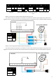
DIP Switches
Terminal block
VII. Product interface definition
Pin Pin name Denion
1
GND Grounding
2
AI1
Analog input 1 –
External temperature sensor
3
AI2 Analog input 2
4
NO4 Relay normal open - HF
5
NO3 Relay normal open - MF
6
NO2 Relay normal open - LF
7
NO1 Relay normal open– ON/OFF
8
B2 Modbus slave B
9
A2 Modbus slave A
10
B1 Modbus host B
11
A1 Modbus host A
12
GND Grounding
13
Vin 9-24V DC input
14
Vout 9-24V DC output
Switch
Number
Switch Denion ON OFF
1
Modbus terminal resistor
2
Modbus slave posion [3]
3
Modbus slave posion [2]
4
Modbus slave posion [1]
5
Modbus slave posion [0]
6
Maximum wind speed [1]
7
Maximum wind speed [0]
8
Control mode selecon
* The above are the default states of DIP switches
Table 1. Terminal block pin funcon denion
Table 2. DIP switch funcon denion
VIII. Wiring diagram – Connecting to the central control unit
The central control unit can read the sensor data of UNOnext and the status of the venlaon equipment via the RS485
physical line and the Modbus RTU protocol