VFD-L Series User Manual 115V 200W-400W 230V 200W-2HP Simple General Purpose AC Drive ASIA NORTH/SOUTH AMERICA EUROPE DELTA ELECTRONICS, INC. DELTA PRODUCTS DELTRONICS (Netherlands) TAOYUAN Plant/ CORPORATION B.V. 31-1, SHIEN PAN ROAD, Sales Office/ Sales Office/ KUEI SAN INDUSTRIAL ZONE P.O. BOX 12173 Industriegebied Venlo Nr. 9031 TAOYUAN 333, TAIWAN 5101 DAVIS DRIVE Columbusweg 20 TEL: 886-3-362-6301 RTP, NC 27709 U. S. A.
Preface Thank you for choosing DELTA’s VFD-L series AC Drive. The VFD-L series is manufactured using high-quality components, material and incorporating the latest microprocessor technology available. This manual will help in the installation, parameter setting, troubleshooting, and daily maintenance of the AC motor drive. To guarantee safe operation of the equipment, read the following safety guidelines before connecting power to the AC motor drive.
Chapter 1 Receiving and Inspection This VFD-L AC drive has gone through rigorous quality control tests at the factory before shipment. Since many things may happen during shipping, please check for the following after receiving the AC motor drive. ◎ Inspect the unit to insure it was not damaged during shipment. ◎ Make sure that the part number indicated on the nameplate corresponds with the part number of your order. Nameplate Information: Example of 1HP230V AC Drive Model Input Spec. Output Spec.
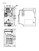
Dimension STOP RUN FWD REV MODE RESET PROG DATA RUN STOP VFD-L MIN. MAX. 0.75KW 230V IPHASE WARNING Do not connect AC power to output terminals (U,V,W). Do not inspect components until LEDs are turned off for at least 1min. Read the user manual before operation.
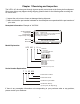
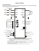
Chapter 2 Wiring Basic Wiring Diagram Users must connect wiring according to the circuit diagram shown below. Please follow all National and State wiring codes, when wiring the VFD-L. Main Circuit Power MCCB R/L1 U/T1 S/L2 S/L2 V/T2 IM 3~ T/L3 T/L3 W/T3 Motor R/L1 +18V Factory default settings Forward/Stop M0 4.7KΩ Reverse/Stop M1 4.7KΩ Reset M2 4.7KΩ Multi-step 1 M3 4.
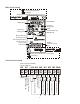
Main circuit wiring AC line input terminals grounding Single phase models input from R/L1, S/L2 R/L1 S/L2 T/L3 UP/DOWN LED display Function Display key Data Confirmation key Frequency setting knob RUN/STOP Motor capacity and input power The signal selection for AVI to input DC0~+10V or 4~20 mA RS485 communication port U/T1 V/T2 W/T3 Motor connections U/T1, V/T2, W/T3 Grounding Control circuit wiring Wire Gauge:22-24AWG Torque: 4Kgf-cm RA RC +10V AVI M0 M1 M2 M3 GND Common signal Multi-function
Wiring Notes: PLEASE READ PRIOR TO INSTALLATION. 1. 2. CAUTION: Do not connect the AC input to any of the U/T1, V/T2, W/T3 terminals, as it will damage the AC drive. ! ! WARNING: Ensure all screws are tightened to the proper torque rating. 3. During installation, follow all national and local electrical, construction, and safety codes for the country the drive is to be installed in. 4.
Chapter 3 Summary of Parameters Group 0: User Parameters aThe parameter may be set during operation. Parameters 0-00 0-01 a 0-02 0-03 a 0-04 a 0-05 0-06 0-07 0-08 Functions Settings Factory Setting Identity code of drive (Read only) 1: 40W 2: 100W 3: 200W 4: 400W 5: 750W 6: 1.5KW Rated current display 40W: 0.4A (Read only) 100W: 0.8A 200W: 1.6A 400W: 2.5A 750W: 4.2A 1.5K: 7.
Parameters a a a a 1-12 1-13 1-14 1-15 1-16 1-17 1-18 Functions Decel time 2 JOG Accel time JOG Decel time JOG frequency Auto-accel/decel S-curve setting in acceleration S-curve setting in deceleration Settings 0.1 ~ 600 Sec 0.1 ~ 600 Sec 0.0 ~ 600 Sec 1.0Hz~400Hz 0: Linear Accel/Decel 1: Auto accel, linear decel 2: Linear accel, auto decel, 3: Auto Accel/Decel 4: Linear accel. Auto decel, stall prevention during deceleration 5: Auto accel.
Group 3: Output Function Parameters Parameters 3-00 3-01 3-02 3-03 Functions Settings Desired freq. attained 1.0 ~ 400 Hz Terminal count value 0 ~ 999 Preliminary count value 0 ~ 999 Multi-function (relay 0: not used output) 1: AC drive operational 2: Max. Output Freq. Attained 3: Zero Speed 4: Over Torque 5: Base-Block (B.B.) 6: Low Voltage Detection 7: AC Drive Operation Mode 8: Fault Indication 9: Desired Freq.
Parameters 4-06 Functions Multi-function input terminal 3(M3) (d 0, d 4〜d 20) Settings 14: increase master freq. 15: decrease master freq. 16: run PLC program 17: pause PLC 18: counter trigger signal 19: counter reset 20: select ACI/deselect AVI Factory setting 7 Group 5: Multi-step Speed and PLC Parameters Parameters 5-00 5-01 5-02 5-03 5-04 5-05 5-06 5-07 5-08 Functions Settings 1st step speed freq. 2nd step speed freq. 3rd step speed freq. PLC mode 0.0 ~ 400Hz 0.0 ~ 400Hz 0.
Parameters 6-04 6-05 6-06 6-07 6-08 6-09 6-10 6-11 6-12 Functions Over-torque detection time Electronic thermal overload relay Electronic thermal characteristic Present fault record Second most recent fault record Third most recent fault record Forth most recent fault record Fifth most recent fault record Sixth most recent fault record Settings 0.1 ~ 10.0 Sec Factory Setting 0.
Parameters Functions 8-08 8-09 8-10 8-11 8-12 8-13 8-14 8-15 Max. allowable power loss time B.B. time for speed search Max. speed search current level Skip freq. 1 upper bound Skip freq. 1 lower bound Skip freq. 2 upper bound Skip freq. 2 lower bound Skip freq. 3 upper bound Skip freq. 3 lower bound Auto restart after fault AVR function 8-16 8-17 Dynamic braking voltage DC braking lower bound limit 8-05 8-06 8-07 Settings Factory Setting 0.3 ~ 5.0 Sec 2.0 0.3~5.0 Sec 0.5 30~200% 150 0.
CHAPTER 4 Troubleshooting and Fault Information The VFD-L AC drive has a comprehensive fault diagnostic system that includes several different alarms and fault messages. Once a fault is detected, the corresponding protective functions will be activated. The following faults are displayed on the AC drive digital keypad. The six most recent faults can be read on the digital keypad display by viewing Pr.6-07 to Pr.6-12. NOTE: faults can be cleared by pressing the Reset key on the keypad or Input Terminal.
Fault Name Fault Descriptions Over-current during acceleration: 1. Short-circuit at motor output. 2. Torque boost too high. 3. Acceleration time too short. 4. AC drive output capacity is too small. Over-current during deceleration: 1. Short-circuit at motor output. 2. Deceleration time too short. 3. AC drive output capacity is too small. Over-current during steady state operation: 1. Short-circuit at motor output. 2. Sudden increase in motor loading. 3. AC drive output capacity is too small.
Standard Specifications Voltage Class 115V 230V 002 004 002 004 007 015 Applicable Motor Output (kW) 0.2 0.4 0.2 0.4 0.7 1.5 0.6 1.0 0.6 1.0 1.6 2.7 1.6 2.5 4.2 7.0 Output Rating Model Number VFD-LA/B Rated Output Capacity (KVA) Rated Output Current (A) Max. Output Voltage (V) 1.6 2.5 3-phase corresponds to double input voltage Three-phase corresponds to input voltage Rated Frequency (Hz) Power Rated Input Current (A) Input voltage Tolerance 1.0~400Hz 6 9 4.9/1.