Operation and Installation manual SOLIVIA 6.0 EU T4 TL SOLIVIA 8.
EN This manual is subject to change. Please check our website at www.solar-inverter.com for the most up-to-date manual version. © Copyright – Delta Energy Systems (Germany) GmbH - All rights reserved. This manual accompanies our equipment for use by the end users.
Table of Contents 1. General Safety Instructions . . . . . . . . . . . . . . . . . . . . . . . . . . .7 2. General Information. . . . . . . . . . . . . . . . . . . . . . . . . . . . . . . .9 2.1 About this Manual . . . . . . . . . . . . . . . . . . . . . . . . . . . . .9 2.2 Safety Symbols & Instruction . . . . . . . . . . . . . . . . . . . . . . .9 2.3 Validity . . . . . . . . . . . . . . . . . . . . . . . . . . . . . . . . . . .9 2.4 Product Description . . . . . . . . . . . . . . . . . . . . . . .
EN 6.2.4 AC Wiring Considerations . . . . . . . . . . . . . . . . . . . . . . . . 39 6.3 DC Connection (from PV array) . . . . . . . . . . . . . . . . . . . . . 39 6.3.1 Asymmetrical Loading . . . . . . . . . . . . . . . . . . . . . . . . . . 42 6.4 Efficiency . . . . . . . . . . . . . . . . . . . . . . . . . . . . . . . . . 44 6.5 Communication Module Connections . . . . . . . . . . . . . . . . . . 48 6.5.1 RS485 Connection . . . . . . . . . . . . . . . . . . . . . . . . . . . . 49 6.5.
7.3.6.4.4 cosφ(P) . . . . . . . . . . . . . . . . . . . . . . . . . . . . . . . . . . . . . . . . . . . . . . . . .76 7.3.6.4.5 Constant Reactive Power. . . . . . . . . . . . . . . . . . . . . . . . . . . . . . . . . . . .79 7.3.6.4.6 Q(V) . . . . . . . . . . . . . . . . . . . . . . . . . . . . . . . . . . . . . . . . . . . . . . . . . . . .79 7.3.6.4.7 LVFRT Low Voltage Fault Ride Through (LVFRT) . . . . . . . . . . . . . . . . .81 7.3.6.5 Reactive Power Control for Slovenia (SONDO) for 15 / 20 / 30 TL . .
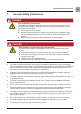
General Safety Instructions 1. General Safety Instructions DanGer risk of death by electrocution Potentially fatal voltage is applied to the solar inverter during operation. This potentially fatal voltage is still present for five minutes after all power sources have been disconnected. ► Never open the solar inverter. ► Always disconnect the solar inverter from power before installation, open the DC isolating switch and make sure neither can be accidentally reconnected.
General Safety Instructions ● The solar inverter is very heavy. The solar inverter must be lifted and carried by at least two people. ● Only devices in compliance with SELV (EN 69050) may be connected to the RS485 and USB interfaces. ● All connections must be sufficiently insulated in order to comply with the IP65 protection rating. Unused connections must be closed by placing cover caps on the solar inverter.
General Information 2. General Information 2.1 about this Manual This manual provides the detail information for the specification, installation procedures and all related functional settings of the solar inverter model. Installation technicians must be well-trained and qualified for installing solar system and must follow all the safety instruction and installation procedures. 2.
General Information Key Features ● Power Rating: 6 / 8 / 10 / 12 / 15 / 20 / 30 kVA ● Power Balancing (33/67) in asymmetrical dc loading situations ● 3-Phase (3-Phase + N + PE), Grid-tie, Transformerless solar inverter ● Maximum efficiency: up to 98.2 % ● Europe efficiency: up to 97.8 % ● Reactive power capability (Cap 0.80 - Ind 0.80) ● Low input current harmonic distortion (THD < 3%) @ full load ● 2 MPP Trackers ● Record up to 30 event logs.
General Information 2.6 additional Information For more detailed information about the SOLIVIA TL series or other related product information, please visit the website at http://www.solar-inverter.com for more support. Solar Inverter Electrical Grid PV Array 3PH DC Distribution Box AC Distribution Box 3-Phase, N, PE Surge arrestor Surge arrestor Fuse AC breaker DC Switch Figure 2.1.: Solar Inverter System Operation Illustration 2.
Preparing for Installation 3. Preparing for Installation 3.1 Instruction before Installing Due to the variety of user installation environments, reading the manual thoroughly before installation is strongly recommended. All the installation and start-up procedures must be undertaken by a professional and well-trained technician. 3.2 Checking the Package There might be some unpredictable situations during transportation. Please check if there is any damage to the cardboard carton.
Preparing for Installation 3.3 Unpacking 1. Open the top of the cardboard box as shown in the figure below. 2. Remove the top packing material after opening the box. 3. Lift the Inverter out of the package and save the packaging in case of return. Figure 3.1.
Preparing for Installation 3.4 Identify the Inverter User can identify the model number by the information on the product label. The model number, specification as well as the series no. is specified on the product label. In regard to the label location, please refer to the below figure. Figure 3.2.: The Type Label 6.0 TL or Figure 3.3.: The Type Label 8.
Preparing for Installation or Figure 3.4.: The Type Label 12 TL and 15 TL or Figure 3.5.
Product Overview 4. Product Overview 4.1 Dimensions SOLIVIa 6.0 TL / 8.0 TL / 10 TL / 12 TL Top view 275 [10.83] Front view Side view 618 [24.3] 625 [24.6] Bottom view Figure 4.1.: Dimensions of SOLIVIA 6.0 TL / 8.
Product Overview 4.2 Dimensions SOLIVIa 15 TL, 20 TL, 30 TL Top view 625 [24.6] Front view 275 [10.83] Side view Bottom view: 15 TL / 20 TL Rear view Bottom view: 30 TL Figure 4.2.
Product Overview 4.3 Function Introduction Inverter exterior features are shown on figure 4.3 and 4.4, and a more detailed description is found in the sections from 4.3.1 to 4.3.3 Air outlets LCD/LED Display Buttons AC Connector Communication Connections *Note: The fan is shown without the required protective screen for illustrative purposes Fan DC Connectors Label Figure 4.3.: 6.0 TL / 8.
Product Overview Air outlets LCD/LED Display Buttons *Note: The fans shown are without the required protective screen for illustrative purposes AC Connector Please note the 15 TL / 20 TL model is shown here. The 30 TL will look slightly different - a different AC connector and 2 addl. DC inputs will be present on the 30 TL. Communication Connections Fan *4 DC Connectors Label Figure 4.4.: 15 TL / 20 TL / 30 TL Inverter Exterior View ➀ Figure 4.5.
Product Overview The chassis has a predrilled hole ➀ to accept a grounding screw as shown. The maximum torque of the M6 grounding screw is 4.4 Nm. There is a 15 mm diameter unpainted surface around the center of the ground screw hole that allows for a solid ground connection when installing the grounding kit. 4.3.1 LCD Display and Buttons LCD Display ESC: ESC MENU UP: MOVE UP ENTER: ENTER MENU OR CONFIRM LED Indicator (GRN/RED) DOWN: MOVE DOWN Figure 4.6.
Product Overview 4.3.2 Inverter Input/Output Interface ➀ ➁ ➂ DC input panel for the 6.0 TL, 8.0 TL, 10 TL, 12 TL, 15 TL and 20 TL has 4 DC inputs. The 30 TL DC input interface shown below, provides 6 DC inputs. SOLIVIA 30 EUT4TL ➃ Figure 4.7.: Input/Output Interface no. ➀ Designation AC connector ➁ ➂ Communication ➃ Fans DC connector Description 400 VAC for 6.0 / 8.0 / 10 / 12 / 15 / 20 TL ; 500 VAC for 30 TL 2 × RS485, 1 × EPO, 2 × Dry contact 4 Strings (6.0 TL / 8.
Product Overview 4.3.3 air outlet air outlet air inlet Figure 4.8.: Air Outlet Illustration There are 4 fans in the bottom section of the inverter and all fans work synchronously. If any one fan locks up or is defective, it will cause a fan failure and power derating. If you suspect that there is a problem with a fan please call the Delta support hotline. Fan Figure 4.9.: Fan Control 6.0 TL, 8.
Product Overview Fan #1 #2 #3 #4 #3 #4 Figure 4.10.: Fan Control 15 TL and 20 TL Fan #1 #2 Figure 4.11.
Installation 5. Installation 5.1 Installing Location The SOLIVIA TL inverters can be installed indoors and in protected outdoor areas due to its enclosure protection classes IP65 and IP55. See the figure 5.1 for further explanation of the protection classes. WarnInG Death and serious injury may occur if the following instructions are not carefully followed ► Do not install the unit near/on flammable objects. ► Do not install the unit at a location that people can gain entry/touch easily.
Installation IP65 protection class IP55 protection class Note: 15 and 20 TL pictured. Other TL models may look slightly different. Figure 5.1.: Protection classes nOTe The fans shown are without the required protective screen for illustrative purposes. The upper section of the inverter, shown in the darker tone above, is sealed from the lower section and rated at IP65 enclosure protection. The lower section of the inverter, containing the cooling mechanisms, is rated at IP55 enclosure protection. 5.
Installation SOLIVIA 6.0 TL / 8.0 TL / 10 TL / 12 TL rear view Wall SOLIVIA 15 TL, 20 TL, 30 TL rear view 6 pcs. screws 6 pcs. screws Unit: mm Note: The wall mount bracket will be the same part for the 6.0 TL / 8.0 TL / 10 TL / 12 TL / 15 TL / 20 TL / 30 TL. Figure 5.2.
Installation Figure 5.3.: Correct and Incorrect Installation Illustration CaUTIOn Machine and equipment damage may occur. ► Please leave an appropriate gap in between when installing single / several DELTA solar inverter systems. ► Please install solar inverters at eye level to allow easy observation for operation and parameter setting. ► Please install solar inverter in a clean and open space. ► The ambient temperature should be between -20°C ... +60°C.
Installation Figure 5.4.: Proper Installation Gap 5.3 ambient temperature The solar inverter can be operated in an ambient temperature between -20 °C ... +60 °C. The following diagram illustrates how the power supplied by the solar inverter is reduced automatically in accordance with the ambient temperature. The device should be installed in a well-ventilated, cool and dry location.
Installation Pout_max (kVA) ~ ~ 15 kVA / 20 kVA ~ ~ -20 -15 40 74 Ambient Temperature (℃) Figure 5.5.: Derating curve for 6.0 TL, 8.
Wiring the Inverter 6. Wiring the Inverter 6.1 Preparation before Wiring 1. To avoid accidents, please confirm that the PV inverter’s power of both DC and AC are switched off. 2. Please confirm whether the input/output of PV inverter’s wiring are clearly indicated. Make sure that the value, polarity, voltage and phase are correct. 3. The wiring procedure of a PV system is shown in figure 6-1 and 6-2. Wiring details are described in the following paragraphs.
Wiring the Inverter PV Array DC Distribution Box DC Wiring Parallel or Separate AC Wiring Communication Wiring Figure 6.1.
Wiring the Inverter PV Array DC Distribution Box (Plus-GND or Minus-GND) or Must be Parallel Connection Must install one transformer per inverter Isolated transformer Utility 3Ph, Δ or Y 230/400 Vac To Inverter 3Ph, Y 230/400 Vac Figure 6.2.
Wiring the Inverter 6.2 aC Grid Connection: 3 Phase + n + Pe WarnInG Death and serious injury may occur ► Before engaging in the AC wiring, please ensure the AC 3-phase power is switched off. 6.2.1 required protective devices and cable cross-sections Please use the proper upstream circuit breaker to protect the inverter according to the table: Model SOLIVIA 6.0 TL Upstream Circuit Breaker 16 A SOLIVIA 8.
Wiring the Inverter If an external residual current device is required, we recommend using a residual current device, type A; see the table. However, be sure to always adhere to the specific regulations applicable in your country. Minimum tripping current of the residual current device Number of inverters 1) 6.0 TL mA 100 2 8.
Wiring the Inverter nOTe TT is not recommended. Have to be sure the voltage of N is very close to PE (< 20 Vrms) 6.2.2 aC bayonet connectors for 6.0 TL, 8.0 TL, 10 TL, 12 TL, 15 TL, 20 TL The AC bayonet connectors are approved for cable sheath diameters between 11 mm and 20 mm. To install an AC cable, first strip the voltage free line and cable ends as shown below and then follow the sequence in Figure 6.5 to assemble the cable and bayonnet connector. 52.5 mm (Pe 57.5 mm) 10 mm Figure 6.3.
Wiring the Inverter The female cable connector needs to be wired as shown below. Rotate the connector housing and cable gland to remove them from the coupling ring. Slide the connector housing and cable gland onto the cable. nOTe: rear view of cable connector L2 To wire the connector refer to placement of L1, L2, L3, N and PE shown to the left. Screw termination is provided to fix the wires to the contacts.
Wiring the Inverter CaUTIOn Machine and equipment damage may occur. ► Observe the pin assignment of the AC bayonet connector. An incorrect assignment can result in the unit being destroyed. The Figure 6.5 pin out diagram shows the connections inside the AC connector. nOTe Make sure the line is provided with a strain relief device. When using cables with a diameter of less than 13 mm (11 mm ... 13 mm diameter cable require strain relief), the cable must be relieved just behind the connector. 6.2.
Wiring the Inverter ➀ ➁ ➂ The female cable connector needs to be wired as shown below. Rotate the connector housing ➀ and cable gland body ➁ and cable gland cap ➂ to remove them from the coupling ring. ➀ ➁ ➂ Cable Slide the connector housing, cable gland body and cable gland cap onto the cable. nOTe: rear view of cable connector To wire the connector refer to placement of L1, L2, L3, N and PE shown to the left. Screw termination is provided to fix the wires to the contacts.
Wiring the Inverter 6.2.4 aC Wiring Considerations The connection to the Amphenol AC connector for all models can be made with a flexible or rigid cable with a copper conductor that has the appropriate cross section according to table 6.1 and which has an installation condition that gives a correction factor equal to one. The AC cable should be protected by a minimum type B 40 Amp breaker and minimum type B 60 Amp breaker for 30 TL.
Wiring the Inverter ➀ ➁ ➂ DC input panel for the 6.0 TL, 8.0 TL, 10 TL, 12 TL, 15 TL and 20 TL has 4 DC inputs. The 30 TL DC input interface shown below, provides 6 DC inputs. SOLIVIA 30 EUT4TL ➃ Figure 6.8.: Input/Output Interface no. ➀ Designation AC connector ➁ ➂ Communication ➃ Fans DC connector Description 400 VAC for 6.0 / 8.0 / 10 / 12 / 15 / 20 TL ; 500 VAC for 30 TL 2 × RS485, 1 × EPO, 2 × Dry contact 4 Strings (6.0 TL / 8.
Wiring the Inverter CaUTIOn Machine and equipment damage may occur. ► The connection number of PV ARRAY, open circuit voltage and power of String_1 and String _2 must be coherent. ► The connection number of PV ARRAY, open circuit voltage and power of String _3 and String _4 must be coherent. ► The maximum open circuit voltage of PV Array must not exceed 1000 V. ► The range of Vmpp of Input DC1 and Input DC2 shall be 350~800 VDC.
Wiring the Inverter 6.3.1 asymmetrical Loading The inverters operate using two separate MPP trackers that can handle both symmetrical and asymmetrical loads to allow for optimum adjustment. This allows for the requirements of complex PV system designs to be fulfilled. For example: east/west-facing roof (symmetrical load) or a south facing roof such as a dormer (asymmetrical load). See the following figures for explanation of how symmetrical and asymmetrical loading are handled: Balanced Input Power Max.
Wiring the Inverter Maximum rating of input power: Model Max. Input Current Max. Power MPPT range Max. Power MPPT range balanced (50/50) unbalanced (33/67) SOLIVIA 6.0 TL 10 A x 2 315 ... 850 VDC 250 ... 850 VDC (33/67%) 420 ... 850 VDC (67/33%) SOLIVIA 8.0 TL 17 A x 2 280 ... 850 VDC 280 ... 850 VDC (33/67%) 330 ... 850 VDC (67/33%) SOLIVIA 10 TL 20 A x 2 350 ... 850 VDC 350 ... 850 VDC SOLIVIA 12 TL 20 A x 2 420 ... 850 VDC 420 ... 850 VDC SOLIVIA 15 TL 24 A x 2 350 ... 800 VDC 470 .
Wiring the Inverter 6.4 Efficiency The best efficiency of the solar inverter is obtained at an input voltage of 640 V. Efficiency [%] 98 96 94 92 90 88 86 84 82 80 0 0.4 0.2 0.6 0.8 1 Power 350 V Figure 6.11.: SOLIVIA 6.
Wiring the Inverter Efficiency [%] 98 96 94 92 90 88 86 84 82 80 0 0.4 0.2 0.6 0.8 1 Power 350 V 640 V 800 V Figure 6.12.: SOLIVIA 8.0 TL Efficiency Curve Efficiency [%] 98 96 94 92 90 88 86 84 82 80 0 0.4 0.2 0.6 0.8 1 Power 350 V 640 V 800 V Figure 6.13.
Wiring the Inverter Efficiency [%] 98 96 94 92 90 88 86 84 82 80 0 0.4 0.2 0.6 0.8 1 Power 350 V 640 V 800 V Figure 6.14.: SOLIVIA 12 TL Efficiency Curve Efficiency [%] 98 96 94 92 90 88 86 84 82 80 0 0.4 0.2 0.6 0.8 1 Power 350 V Figure 6.15.
Wiring the Inverter Efficiency [%] 98 96 94 92 90 88 86 84 82 80 0 0.4 0.2 0.6 0.8 1 Power 350 V 640 V 800 V Figure 6.16.: SOLIVIA 20 TL Efficiency Curve Efficiency [%] 98 96 94 92 90 88 86 84 82 80 0 0.4 0.2 0.6 0.8 1 Power 350 V 640 V 800 V Figure 6.17.
Wiring the Inverter 6.5 Communication Module Connections The communication module supports the communication functions with a computer, also provides 1 EPO (Emergency Power Off) and 2 sets of dry contacts. The parts of the communication module are shown in Figure 6.15. The function of each part is detailed in sections 6.5.1 ... 6.5.3. 1. 2. 3. 15 TL / 20 TL / 30 TL 6.0 TL / 8.
Wiring the Inverter 1. Unscrew and remove the two Phillips screws highlighted above in Figure 6.15. 2. Remove the front plate as shown. 3. Carefully pull out the communication module from the inverter. Remove glands and plugs where applicable. 6.5.1 rS485 Connection The pin definition of RS485 is shown in Table 6.3. The wiring of multi-inverter connections is shown in Figure 6.16. PIn 4 7 8 FUnCTIOn GND DATA+ DATA- Table 6.3.
Wiring the Inverter Figure 6.20.: Terminal resistor switch for Multi-inverter Connection To engage the internal Terminal Resistor, place switch number 2 on the communication module in the on position. See figure 6.17 for more information. Baud Rate Data Bit Stop Bit Parity Programmable, 2400/4800/9600/19200/38400, default = 19200 8 1 N/A Table 6.4.: RS485 Data Format 6.5.2 ePO (emergency Power Off) Connections The SOLIVIA TL inverters provide two sets of emergency power off functions.
Wiring the Inverter nOTe To shutdown the inverter, short pin 1 and 2 or short pin 4 and 5. 6.5.3 Dry Contact Connection Provides 2 sets of Dry Contact functions - NO1 and NO2. Please refer to Figure 6.16 for connection diagram and read below for more details. NO1: When a fault is detected, COM and NO1 will be shorted. NO2: When the inverter is on grid, the COM and NO2 will be shorted. COM NO1: Fault NO2: On Grid Figure 6.21.
Operating the PV inverter 7. Operating the PV inverter WarnInG Burn hazard! The enclosure temperature may exceed 70° C while in operation. Injury may occur owing to the hot surface. ► Please do not touch! After installation, please confirm the AC, DC, and Communication connections are correct. Follow the steps below to startup the inverter: 1. 2. Check the PV array DC voltage: – Uncover the PV arrays and expose them to full sunlight.
Operating the PV inverter Grid (as shown on the Display) Description Australia Australia AS 4777 Belgium 6 TL 8 TL Belgium as per C10/11, June 2012 Bulgaria 10 TL 12 TL 15 TL 20 TL 30 TL x x x x x x x x x x x x x x x x x x x x x Bulgaria as per VDE 0126 Czech Czech Republic as per VDE 0126-1-1 Denmark Denmark as per VDE AR N 4105 France x France as per UTE 15 712-1 France (60Hz) France VFR 2013 French Islands 60 Hz France - VDE 0126-1-1 / A1 with x x x x x x x
Operating the PV inverter nOTe ► If selecting Germany or Italy as the country, it could be necessary to adjust active and reactive power settings (Information for the settings will come from the local grid operator). ► If needed please call the local support hotline for assistance in setting up Germany MVD/LVD or Italy CEI 0-21 / A70 grid settings. 4.
Operating the PV inverter Inverter Status Standby or Countdown Power ON Error or Fault Night time (No DC) Bootloader mode Green LeD red LeD FLASHING - on 1 sec. and off OFF 1 sec. ON OFF OFF ON OFF OFF FLASHING - on 1 sec. and off 1 sec., first the green LED then the red LED in alternating sequence Table 7.1.: LED indicator 7.1 Disconnection Parameter Settings 7.1.1 Power Disconnection Device (PDD) Settings This applies to LVD and MVD settings when selecting the grid as DE LVD or DE MVD.
Operating the PV inverter At any time, while you are viewing one of the 4 grid setting windows, you are able to switch off the power disconnection device by simultaneously pressing the up and down buttons and holding for more than 5 seconds. See the tables below for the LVD/MVD allowed parameter ranges according to the regulations: When the selected grid is LVD, the following adjustable vaules are allowed: Parameter Rise-in-voltage protection U> name in display Umax adjustable values 110 ...
Operating the PV inverter 7.2 Home Page When the inverter is operating normally, the LCD will show the home page as shown in Figure 7.4. On the home page the user can find the output power, inverter status, E-today, date and time. Today Power Today Runtime Date and Time Actual Power Inverter Status Today Power Curve Figure 7.4.: Home page 7.3 LCD Flow Chart Press any button to enter the menu page, the selections are shown in Figure 7.5.
Operating the PV inverter “„7.3.1 Power Meter“ on page 58 “„7.3.2 Statistics“ on page 58 “„7.3.3 Logs“ on page 59 “„7.3.4 Actual data“ on page 60 “„7.3.5 Inverter Information“ on page 61 “„7.3.6 Settings“ on page 61 7.3.1 Power Meter Figure 7.6.: Power Meter Pages 7.3.2 Statistics After pressing enT on this page, the user can view the historical data about power generation on a yearly, monthly and daily basis.
Operating the PV inverter Figure 7.7.: Statistics Pages 7.3.3 Logs After pressing enT on this page, the user can view the internal log and can view the events log. 7.3.3.1 Internal Data The internal data shows all messages coming from the inverter. These messages indicate the status of internal processes and also changes on the AC and DC terminals, for example: frequency, voltage, etc. Figure 7.8.: Internal Data Flow Chart 7.3.3.
Operating the PV inverter Figure 7.9.: Events Journal Flow Chart 7.3.4 actual data Actual data includes 4 pages and records the maximum and/or minimum historical values, including voltage, current, power and temperature. Figure 7.10.
Operating the PV inverter 7.3.5 Inverter Information This page includes the following information: serial number, firmware version, installation date, and inverter ID. To change the inverter ID, please refer to “„7.3.6.2 Install Settings“ on page 62. Figure 7.11.: Inverter Information Page nOTe The information shown in Figure 7.11 is for illustration purposes and may not match the actual information displayed on your inverter. *The last menu items are only applicable for installations in Italy.
Operating the PV inverter nOTe FRT is only accessible if you have selected Germany MVD, Italy CEI 021 or A70 as your grid selection. 7.3.6.1 General Settings Settings in the General Settings include Language, Date, Time, Screen Saver, Brightness, Contrast, Baud Rate, CO2 saved, Earning Value, and Currency. Figure 7.13.: General Settings Page User can set the Language, Date, Time, Screen Saver, LCD Brightness, and Contrast appear on the General Settings page 1.
Operating the PV inverter Password is 5555. Figure 7.14.: Install Settings Page - Installer Mode ● Inverter ID: This setting is used to set unique ID‘s for installations with more than one inverter. In a multi-inverter installation where the inverters will be in a network, each inverter must have a unique ID. ● Insulation: ON means enable the measurement of impedance between Array and PE, will not connect to Grid if failure.
Operating the PV inverter Feature Power limit available for LVD MVD x x Power vs. frequency x x x x x x Reactive power control Constant cos φ cos φ (p) Constant reactive power x Q (V) x Description To reduce the maximum power production To set the power gradiant in dependency of the frequency To set a fixed cos φ (inductive or capacative) To set a cos φ (inductive or capacative) in dependency of the active power ratio P/Pn To set the reactive power ratio Q/Sn. For MVD grids only.
Operating the PV inverter CaUTIOn Machine and equipment damage may occur. ► Please only adjust active and reactive power settings if you are a qualified electrical technician with the knowledge to do so ► Adjustments may affect energy production ► Some values entered in the Active/Reactive Power settings must come from the local grid operator. Please check with them before making any adjustments 7.3.6.3.1 Power Limit User can select set percentage of actual or rated power to limit inverter’s output power.
Operating the PV inverter output power 100% available power A When Actual Power is selected the output power is based on the percentage of the available power (dotted path) If the set point is 75% then B=75% of A. output power 75% B 50% 25% 0% 4:00 output power 100% 75% 8:00 12:00 16:00 20:00 00:00 When Rated Power is selected the output power is equal to the nominal output power x the Set Point. If set at 75% then output power can not exceed 75% of nominal power.
Operating the PV inverter P P Pm Gradient (%/Hz) fstart fstop f(Hz) Figure 7.19.: LVD Curve power vs. frequency Pm Gradient (%/Hz) frecovery fstart fstop f(Hz) Figure 7.20.: MVD Curve power vs. frequency nOTe The Power vs Frequency function is required for LVD and MVD. Please make sure the Mode is ON and do not turn off. Figure 7.21.: Power vs. Frequency adjustable parameters Parameter Actual / Rated Power Start frequency Stop frequency adjustable Values Recovery frequency 50.00 ... 55.
Operating the PV inverter 7.3.6.3.3 Constant cos φ This feature is available for LVD and MVD grids. This feature allows the user to set up a constant cos φ. Figure 7.22.: Constant cos φ settings page adjustable parameters Parameter cos φ Mode adjustable values inductive | capacitive Ind 0.8 ... Ind 0.99, 1, Cap 0.8 ... Cap. 0.99 ON | OFF Description Sets the cos φ to the adjusted value. Switches the feature on and off 7.3.6.3.4 cosφ(P) This feature is available for LVD and MVD grids.
Operating the PV inverter Figure 7.23.: cos φ(P) settings page adjustable parameters Parameter Upper limit - cos φ adjustable values Ind 0.80 ... Cap 0.80 Lower Power Lower limit - cos φ Upper Power 0 ... 100 % Ind 0.80 ... Cap 0.80 0 ...
Operating the PV inverter Figure 7.24.: Constant Reactive Power settings page adjustable parameters Parameter Reactive power Q/Sn Mode adjustable values -60 ... +60% inductive | capacitive ON I OFF Description Reactive power ratio in relation to apparent power. This switches the feature on and off 7.3.6.3.6 Q(V) This feature is available for MVD grids only.
Operating the PV inverter Figure 7.25.: Q(V) settings page adjustable parameters Parameter Lower Q/Sn Menu name Qi Limit Description Must be within the range Ind 60% ... Cap 60% V2i adjustable values 0 ... 60% inductive | capacitive 0 ... 60% inductive | capacitive 184 ... 264 V Upper Q/Sn Qs Limit Lower capacitive point Upper capacitive point Lower inductive point Upper inductive point Delay time Lock-in Power Lock-out Power Mode V1i 184 ...
Operating the PV inverter ➀ ➁ ➂ ➃ ➀ ➁ ➂ ➃ No instability or disconnection from the network Feed-in reactive current depends on K factor Same as area 2, Feed-in reactive current depends on K factor Disconnects from the network Figure 7.26.: Fault Ride Through settings page adjustable parameters Parameter Dead band - Vhigh Dead band - Vlow K factor Vdrop t1 U1 t2 t3 Mode 72 adjustable values +0 ... +20 % -20 ... 0 % 0 ... 10 0 ... 90% 0 ... 500 ms 20 ... 90% 0.01 ... 5 s 0.01 ...
Operating the PV inverter 7.3.6.4 Active/Reactive Power control for Italy CEI 0-21 and Italy A70 Below is an overview of the features that are adjustable to control the production of active and reactive power for Italy CEI 0-21 and Italy A70. Italy CEI 0-21 is applicable for low voltage grids and A70 is applicable for medium voltage grids. Feature Active power control Power limit Power vs.
Operating the PV inverter Note: Before adjusting the Active/Reactive Power settings, a Warning window will be displayed, that you should read and make a selection to continue or to quit. Please see caution messages related to adjusting the settings. CaUTIOn Machine and equipment damage may occur.
Operating the PV inverter adjustable parameters Parameter Set point adjustable Values 0 ... 100% Actual/Rated Mode Actual | Rated ON | OFF Description Sets the power reduction to the adjusted value. The value is multiplied with the value of the Locked power limitation. Select Actual or Rated Power Switches the feature on and off. 7.3.6.4.2 Power vs. Frequency This function is available for CEI 0-21 and A70. The figure below explain the behavior of this function.
Operating the PV inverter nOTe The Power vs Frequency function is required for CEI 0-21 and A70. Please make sure the Mode is ON and do not turn off. *Recovery Frequency is defined in the grid setting parameters 49.9 - 50.1 Hz by default. Figure 7.30.: Power vs. Frequency adjustable parameters Parameter Actual / Rated Power Start frequency adjustable Values 50 - 55 Hz Stop frequency Recovery frequency Gradient Recovery time Mode Nonadjustable 2.0 ... 5.
Operating the PV inverter cosφ 1 = 1 P/Pn inductive capacitive 0.9 0.9 Figure 7.31.: cosφ(P) graph There are two possible curves defined in the cosφ(P) graph, curve A in blue (the default) and curve B in red. Pn = nominal power Curve a (in blue on Figure 7.31) A is identified from Plock-out = value from local grid operator and cosφ = 1 B is identified from Plock-in = value from local grid operator and cosφ = 1 C is identified from P = Pn and cos = cosφmax Curve B (in red on Figure 7.
Operating the PV inverter notes: In the formulas on the previous page, the parameters mentioned are named differently as in the menu page Curve a (in blue) Figure 6.30 Point A = Plockout = Lower Power Point B = Plockin = Upper Power Point C = Lower limit • cosφ Curve A is followed when Lower Power is not equal to Upper Power Curve B (in red) Figure 6.30 Point A (Lower Power) = Point B (Upper Power) Point C = Lower limit • cosφ Curve B is followed when Lower Power = Upper Power Figure 7.32.
Operating the PV inverter Parameter Mode adjustable values ON I OFF Curve a Curve B This switches the feature on and off. Default mode is OFF. *These values are only adjustable if Country setting is Italy CEI-021 or Italy A70. This means the inverter will feed in reactive power depending on the active power once the grid voltage is higher than Lock-in Voltage. When grid voltage is lower than Lock-out voltage then inverter would go back to pure active power control.
Operating the PV inverter Vmax = 1.1 Vn V V V1 = 1.08 Vn V 2s V 1s V 2s V 1s -Q max Q max Q -Q max V 1i V 1i V 2i Curve A V 2i V2 = 0.92 Vn Vmin = 0.9 Vn Qr Q max Qr Curve B Figure 7.34.: Q(V) Note: Qs limit and Qi limit are calculated based on Q/Sn. Figure 7.35.
Operating the PV inverter adjustable parameters Parameter Qs limit (Q/Sn) V1s V2s V1i V2i Plock-in* adjustable values 0 ... 60% inductive | capacitive 0 ... 60% inductive | capacitive 230 ... 264.5 V 230 ... 264.5 V 184 ... 230 V 184 ... 230 V 10 ... 100% Plock-out* 5 ... 10% Delay time Mode 0 ... 120 s Curve A I Curve B I OFF Qi limit (Q/Sn) Description Ind 44% Cap 44% 248.4 V 253 V 211.
Operating the PV inverter Figure 7.37.: Fault Ride Through settings page adjustable parameters Parameter Dead band - Vhigh Dead band - Vlow K factor Vdrop t1 U1 t2 t3 Mode 82 adjustable values +0 ... +20 % -20 ...
Operating the PV inverter 7.3.6.5 reactive Power Control for Slovenia (SOnDO) for 15 / 20 / 30 TL When selecting Slovenia from the Country setting list on initial start up, it is possible to adjust reactive power parameters for Q(V) according to two curves, class B and class C. The Slovenian requirements are known as SONDO or SOIEDN (System operation instructions for electricity distribution network). Q(V) is the reactive power ratio Q/Sn in dependency of the voltage V.
Operating the PV inverter R eactive Power Control a V1s b V2s c Qs limit d V1i e V2i f Qi limit 21. Jun 2010 13:50 [ 230 ] V [ 236 ] V [ Ind 15 ] % [ 230 ] V [ 207.0 ] V [ Cap 60 ] % R eactive Power Control 21. Jun 2010 13:50 Delay Time [ 10 ] s Lock-in Power [ 0 ] % Lock-out Power [ 0 ] % Mode [ ClassB ] [ Class B ] [ Class C ] [ Off ] Figure 7.40.
Maintenance 8. Maintenance In order to ensure the normal operation of the PV Inverter, please check it regularly at least once every 6 months. Check that all the terminals, screws, cables are securely in place. If there are any damaged parts, please contact a qualified technician to repair it or to replace it with a new spare part. To ensure that no foreign contaminants enter the warm air outlets, please have them cleaned every 6 months by qualified technicians.
Maintenance 1. 2. 3. 4. Figure 8.1.
Maintenance 8.2 replace a Fan assembly If one of the fans has failed it is necessary to order a new fan assembly and replace it. User should remove the fan bracket with faulty fan as shown in figure 8.1. Four thumb screws (circled below) attach the fan bracket to the inverter. Loosen the 4 thumb screws and pull the fan bracket from the inverter carefully and then disconnect the four pairs of fan electrical connectors (or single pair of fan electrical connectors for 6.0 / 8.0 / 10 / 12 TL).
Maintenance Designation FAN ASSEMBLY FOR SOLIVIA 30 TL Part number Delta EOE90000531 Table 8.1.: Fan Assembly Part Numbers 8.3 Cleaning the air Outlets Figure 8.3 shows the removal of the vent covers for cleaning. First remove the 4 screws that hold the vent cover to the inverter enclosure. Next, remove the vent cover from the inverter. With the vent cover removed, clean it on both sides. After cleaning one of the vents, proceed to take off the vent on the opposite side and clean in the same manner.
Measurements and Messages 9. Measurements and Messages 9.1 Measurements A C B Figure 9.1.: Measurements on the Home Page A B C Measurement E-Today Runtime Power Description Total energy generated today Total PV inverter operation time for the day Actual power being generated Table 9.1.
Measurements and Messages D E F A B C J K L M G H B I Figure 9.2.
Measurements and Messages B A C E D F H B G I Figure 9.3.
Measurements and Messages G H B I J K L M N O A B C D E F P Q R Figure 9.4.: Measurements on the Actual Data Pages A B C D E F G Measurement Input 1 Volt. maximum Input 1 I maximum Input 1 P maximum Input 2 Volt. maximum Input 2 I maximum Input 2 P maximum L1 Volt.
Measurements and Messages Table 9.4.: Actual Data Pages Measurement and Description A C E G B D F H B Figure 9.5.: Measurements of Temperature on the Actual Data Pages A B C D E F G H Temperature Inside max. Inside min. Heatsink-1 max. Heatsink-1 min. Heatsink-2 max. Heatsink-2 min. Heatsink-3 max. Heatsink-3 min.
Measurements and Messages 9.
Measurements and Messages Message Relay Test Open Bus Unbalance HW Bus OVR HW Bus UVR AC Current High HW CT A Fail HW CT B Fail HW CT C Fail HW AC OCR Inverter Failure HW ZC Fail DC Current High Warnings HW FAN Solar1 Low Solar2 Low Red LED on Red LED blinks X X X Description One or more relays are defective - open Bus voltage is unbalanced BUS or BUS+ or BUS- voltage is over rating BUS+ or BUS- voltage is under rating X X X X X X X X X Phase-L1, L2, or L3 current is over rating Current sensor-L1 fail
Troubleshooting 10. Troubleshooting LED Indicator (Green/Red) Green - ON: Operating Blinking: Countdown Red - ON: Error/Fault Blinking: Warning Figure 10.6.
Troubleshooting Message HW Connect Fail red LeD on X red LeD blinks Solution ► ► No Grid X ► AC Volt Low X ► AC Volt High X ► ► Solar1 High X ► ► Solar2 High X ► Faults HW DC Injection X ► ► Temperature X ► HW NTC1 Fail X ► HW NTC2 Fail X ► HW NTC3 Fail X ► HW NTC4 Fail X ► Firmware Fail X ► HW DSP ADC1 X ► HW DSP ADC2 X ► HW DSP ADC3 X ► HW Red ADC1 X ► Check the AC connection, must be according to the manual instructions Please contact your installation
Troubleshooting Message HW Red ADC2 red LeD on X red LeD blinks Solution HW Efficiency X ► HW COMM2 X ► HW COMM1 X ► Ground Current X ► ► ► ► Insulation X ► ► HW Connected Fail X ► RCMU Fail X ► Relay Test Short X ► Relay Test Open X ► Bus Unbalance X ► ► ► HW Bus OVR X ► ► ► ► AC Current High X ► HW CT A Fail X ► HW CT B Fail X ► 98 Please contact your installation technician or DELTA tech.
Troubleshooting Message HW CT C Fail red LeD on X HW AC OCR X ► Inverter Failure X ► HW ZC Fail X ► DC Current High X ► Warnings HW FAN red LeD blinks Solution ► X ► Solar 1 Low X ► ► ► Solar 2 Low X ► ► ► Please contact your installation technician or DELTA technical support if it will not go back to normal operation Please contact your installation technician or DELTA technical support if it will not go back to normal operation Please contact your installation technician or DELTA
Decommissioning 11. Decommissioning Decommissioning Procedure If it is necessary to put the SOLIVIA TL out of operation for return or maintenance, please follow the instructions below: WarnInG Death and serious injury may occur. To avoid injuries, please follow the below procedures: 100 1. Switch off AC circuit breaker to disconnect with electrical grid. 2. Switch off the DC Disconnect switch to disconnect with DC power input. 3.
Technical data 12. Technical data 12.1 Specification 6.0EUT4TL INPUT (DC) Max. recommended PV power 1) Recommended PV power range Nominal power Operating voltage MPP Voltage range Symmetrical load (50/50%) Asymmetrical load (67/33%) Asymmetrical load (33/67%) Nominal voltage Start up power Maximum voltage Number of inputs Max. current Overvoltage category 2) OUTPUT (AC) Max. apparent power 3) Nominal apparent power Voltage range (3 phase) 3) Nominal current Max.
Technical data Humidity Max. Operating Altitude MeCHanICaL DeSIGn Size (L x W x D) Weight Enclosure Cooling AC connector DC connector pairs Communication interfaces DC disconnector Display STanDarDS / DIreCTIVeS Protection degree 5=) Safety class Configurable trip parameters Insulation monitoring Overload behavior Safety Grid Interface EMC 1) 2) 3) 3) 5) % m 6.0eUT4TL 8.0eUT4TL 5 ...
Technical data InPUT (DC) Max. recommended PV power 1) kWP Recommended PV power range kWP Nominal power kW Operating voltage VDC MPP Voltage range Symmetrical load (50/50%) VDC Asymmetrical load (67/33%) VDC Asymmetrical load (33/67%) VDC Nominal voltage VDC Start up power W Absolute maximum V voltage Number of inputs Max. current Overvoltage category 2) OUTPUT (aC) Max. apparent power 3) Nominal apparent power Voltage range (3 phase) 3) Nominal current Max.
Technical data 15eUG4TL MeCHanICaL DeSIGn Size (L x W x D) Weight Enclosure Cooling AC connector 20eUG4TL mm 952 x 625 x 275 kg 67.2 67.2 Powder coated aluminum Fan Amphenol C16-3 DC connector pairs 4 Multicontact MC4 Communication interfaces DC disconnector Display STanDarDS / DIreCTIVeS Protection degree 5) Safety class Configurable trip parameters Insulation monitoring Overload behavior Safety 2 RJ45 / RS485 Grid Interface EMC 1) 2) 3) 3) 5) 30eUT4TL 72.
Technical data 12.2 Cable recommendations Power wiring Current rating Cross-section AC - < 40 A (8.0 TL / 10 TL / Calculated based on needed 12 TL / 15 TL / 20 TL) length, used material, cable < 60 A (30 TL) losses and etc. 2 DC 34 A 6 mm Communication cable RS485 modular communication cable / cross wired 8 poles Recommended max.
Technical data 12.3 earthing Systems Figure 12.1.
Technical data 12.4 15 TL and 20 TL Models With earlier DC Input Panel Please note that 15 TL and 20 TL inverter models have two different DC input connector configurations, while the models are operationally the same and the DC connectors are the same type. Please see the figures below for the layout of the DC inputs for 15 TL and 20 TL models produced before and after September 1, 2012. DC 1 DC 2 Figure 12.2.: DC Input Panel For Models Before Sept. 1, 2012 Figure 12.3.
13.
Please visit the web site at www.solar-inverter.com to find all applicable certificates for the SOLIVIA TL solar inverters.
SUPPOrT - eUrOPe and aUSTraLIa austria Poland service.oesterreich@solar-inverter.com 0800 291 512 (Free Call) service-pvs@delta-es.pl +48 22 335 2619 Belgium Portugal support.belgium@solar-inverter.com 0800 711 35 (Free Call) suporte.portugal@solar-inverter.com +49 7641 455 549 Bulgaria Slovakia support.bulgaria@solar-inverter.com +421 42 4661 333 podpora.slovensko@solar-inverter.com 0800 005 193 (Free Call) Czech republic Slovenia podpora.czechia@solar-inverter.