1 TR Operation and installation manual for SOLIVIA 11 EU G4 TR EU
This manual is for SOLIVIA 11 EU G4 TR solar inverters with software version 1.2.8. This manual is subject to change. Please check our website at www.solar-inverter.com for the most up-to-date manual version. Delta Energy Systems (Germany) GmbH Tscheulinstrasse 21 79331 Teningen Germany © Copyright – Delta Energy Systems (Germany) GmbH - All rights reserved. This manual accompanies our equipment for use by the end users.
Table of contents 1. About this manual . . . . . . . . . . . . . . . . . . . . . . . . . . . . . . . . 7 1.1 Purpose of this manual . . . . . . . . . . . . . . . . . . . . . . . . . . 7 1.2 Target group of this manual . . . . . . . . . . . . . . . . . . . . . . . . 7 1.3 Warnings and symbols . . . . . . . . . . . . . . . . . . . . . . . . . . 8 1.4 Writing conventions . . . . . . . . .
5. Operating behavior . . . . . . . . . . . . . . . . . . . . . . . . . . . . . . . 24 5.1 Technical structure of the solar inverter . . . . . . . . . . . . . . . . . 24 5.2 Operation method . . . . . . . . . . . . . . . . . . . . . . . . . . . . 25 5.3 Data evaluation and communication . . . . . . . . . . . . . . . . . . . 26 6. Installation . . . . . . . . . . . . . . . . . . . . .
9.3 User settings . . . . . . . . . . . . . . . . . . . . . . . . . . . . . . . 71 9.3.1 Overview . . . . . . . . . . . . . . . . . . . . . . . . . . . . . . . . . 71 9.3.2 Active power control . . . . . . . . . . . . . . . . . . . . . . . . . . . 72 9.3.2.1 Overview . . . . . . . . . . . . . . . . . . . . . . . . . . . . . . . . . . . . . . . . . . . . . . . . . 72 9.3.2.2 Power reduction . . . . . . . . . . .
11.2.2 Other LED and display messages . . . . . . . . . . . . . . . . . . . . 95 11.3 View grid setup . . . . . . . . . . . . . . . . . . . . . . . . . . . . . . 95 11.4 Maintenance . . . . . . . . . . . . . . . . . . . . . . . . . . . . . . . 96 12. Repair . . . . . . . . . . . . . . . . . . . . . . . . . . . . . . . . . . . . . . 97 12.1 Replacing fan . . . . . . . . . .
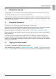
1. About this manual Congratulations on the purchase of the technically advanced solar inverter SOLIVIA EU G4 TR. This manual will help you become familiar with this product. Please observe the safety regulations of the individual countries. Careful handling of your product will contribute to its service life durability and reliability. These are essential prerequisites for maximum yield from your product. 1.1 Purpose of this manual This manual is part of the product. Keep this manual in a safe place.
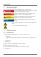
About this manual 1.3 Warnings and symbols Here, you will find explanations for the warnings and symbols used in this manual. danger Indicates a hazardous situation. If not prevented, an accident will result in death or serious injury to humans. warning Indicates a hazardous situation. If not prevented, an accident could result in death or serious injury to humans. Caution Indicates a hazardous situation. If not prevented, an accident could result in moderate or minor injury to humans.
1.4.2 User buttons and LEDs User buttons are referenced in bold type: Esc button. LEDs alarms on the device are referenced in italic type: Failure LED 1.4.3 Software Software menu items are shown as: User settings menu. Input fields are used to change the value of a parameter. Any kind of input field in the display is marked like: Cos phi input field.
Intended use 2. Intended use The solar inverter connects a photovoltaic system to the public grid. The solar inverter converts direct current into alternating current, which is fed into the public grid. This European solar inverter can be used in the following countries: Belgium, Czech Republic, France, Germany, Greece, Italy, Portugal, Spain and United Kingdom. (This list is still under the regulatory procedure.) The solar inverter is for use in grid-connected photovoltaic systems.
●● Sufficient cooling is necessary. ●● The solar inverter is heavy (see “13. Technical data”, p. 99). This can cause injury when not handled correctly. ●● The unit has a high leakage current (see “13. Technical data”, p. 99). The PE conductor MUST be connected prior to commencing operation. ●● To the RS485, USB and I/O interfaces only devices according to SELV (EN 69050) may be connected. ●● Do not remove warning labels that are attached to the solar inverter by the manufacturer.
System description 4. System description 4.1 Scope of delivery ●● Solar inverter ●● Mounting plate ●● Operation and installation manual ●● Amphenol AC connector ●● 2 M6 nuts and 2 M6 washers ●● Connector for the I/O interface ●● Labels “Power limitation” 4.2 General overview ➀ ➁ ➂ ➃ ➄ Image 4.1.: Components of the solar inverter No. Designation Description ➀ ➁ ➂ ➃ ➄ Status LEDs “4.4 Status LEDs”, p. 14 Display and buttons “4.5 Display and buttons”, p. 14 Type label “4.
Type label 400-900V 425-800V 1000V 29A 29A DC operating volt. range: DC operating volt. range (MPP): DC max. input voltage: DC max. operating current: DC max. current per string: AC nom.output voltage: AC nom.output frequency: AC max. continuous output current: AC max. continuous output power: AC reactive current: 3x400V~3P+N+PE wye connected 50Hz 3x20.0A 11.0kVA Cap 0.8 ~Ind 0.
System description 4.4 Status LEDs Operation ➀ ➁ ➂ Earth Fault Failure Image 4.3.: No. Label ➀ ➁ ➂ Designation Color Operation Operation Green Earth Fault Earth fault Red Failure Failure Yellow Status LEDs For LED messages, see “13.1.3 Display messages”, p. 74. 4.5 Display and buttons 4.5.1 Components ➀ ➀ ➁ Display Buttons for display ➁ ESC Image 4.4.: Components of the display Display layout Format Continue ➔Date: DD.MM.YYYY Time: 12h Image 4.5.
Display buttons Sign ESC Usage To exit a menu and to cancel an input without accepting an adjusted value Designation in manual Esc To move in a menu and to adjust values Up To move in a menu and to adjust values Down To select a menu entry and to confirm an input with accepting the adjusted value Enter 4.5.2 Operating the display 4.5.2.1 Menu structure The menus can have up to three levels: [Main menu] ...
System description 4.5.2.2 Go-to function NOTE To go directly to a specific menu in the display, you can use the Go-to function of the solar inverter. For a list of available menu numbers, see “14.3 Overview menu structure”, p. 106 1. To open the Go to menu, press the Esc button on the solar inverter for at least 3 seconds. →→ The Go to menu is opened. 03 Go to menu ➔ 2. Menu: 000 To enter a menu number, press the Enter button. →→ The first digit is flashing. 3.
4.5.2.3 Moving in menus To move in a menu, use the Up/Down buttons. Solivia ## G4 Production info ➔User settings Diagnostic&Alarm Use the Down button to move to the next lower menu entry and the Up button to move to the next upper menu entry. Solivia ## G4 User settings ➔Diagnostic&Alarm Inverter info Solivia 11 G4 Diagnostic&Alarm ➔Inverter info Short cut 4.5.2.4 Selecting a menu entry ►► To open a menu entry, press the Enter button.
System description 4.5.2.5 Leaving a menu ►► To get back to the parent menu, press the Esc button. Initial display Press Button 400 Production info Feed-in settings ➔Actual data Day statistics 4.5.2.6 ESC Result Esc Solivia ## G4 User features ➔Production info User settings Adjusting values There are several menues where you have to adjust parameters. To change a parameter value, the Up/Down buttons are used. The example shows the procedure to change a value.
Use buttons Action 4. Press Enter to open the menu 110 Date & time. Result 110 Date & time Format ➔Date: 09/14/2011 Time: 03:15:22pm 5. When necessary, press the Up/ Down buttons to select the menu entry Date. 110 Date & time Format ➔Date: 09/14/2011 Time: 03:15:22pm 6. To start adjusting, press Enter. 110 Date & time Format ➔Date: 09/14/2011 Time: 03:15:22pm →→ The digits for month are flashing. 7. Press the Up/Down buttons to adjust the month.
System description Use buttons Action þþ The value is taken over and the editing mode is left. 4.5.3 Result 110 Date & time Format ➔Date: 11/17/2012 Time: 03:15:22pm Short cuts The table shows special short cuts for the display buttons. Use buttons ESC Action Pressing Esc and Down button at the same time opens the menu 100 Installation to select the display language, see “9.1.1 Language”, p.
4.6 Electrical connectors 4.6.1 Overview ➆ ➅ ➄ ➃ ➂ ➀ Image 4.6.: ➁ Electrical connectors No. Designation Description ➀ ➁ ➂ ➃ ➄ ➅ ➆ DC connectors “4.6.2 DC connectors and DC switch”, p. 22 AC connector “4.6.3 AC connector”, p. 22 Fan connector “4.7 Fan”, p. 23 2 x RS485 interfaces “4.6.4 RS485 (EIA485) interface”, p. 22 USB interface “4.6.5 USB interface”, p. 23 I/O interface “4.6.6 I/O interface”, p. 23 DC switch “4.6.2 DC connectors and DC switch”, p.
System description 4.6.2 DC connectors and DC switch DC+ Image 4.7.: DC– DC connectors and DC switch The DC connectors are used to connect the string(s) of PV modules to the solar inverter. The solar inverter has an integrated DC switch to disconnect the DC connectors from the DC voltage of the PV modules. The maximum input current load of each individual Multi-Contact MC4 connector is 29 A. Type of connector: Multi-Contact MC4 connectors; 3 x for DC negative, 3 x for DC positive 4.6.
Each solar inverter must have a unique ID, on the last one in a series the termination has to be switched on. This can be done either during (see “7. Commissioning”, p. 45) or later on (see “9.1.6 RS485 (EIA485)”, p. 69). Type of connector: 2 x RJ45 4.6.5 USB interface The USB interface is used for saving and loading data and reports.
Operating behavior 5. Operating behavior 5.1 Technical structure of the solar inverter The solar inverter is galvanic isolated from the grid through a DC/AC converter with an integrated high-frequency transformer. MPP-tracking The solar inverter has one MPP tracker (MPP = Maximum Power Point). The MPP tracker is used to adjust the DC voltage depending on the varying solar irradiation levels and ambient temperatures. So the maximum power output of the PV modules can be achieved.
Efficiency 0.97 0.95 0.91 0.89 0.87 0.85 4000 2000 0 6000 8000 10000 Power [W] 425 V Image 5.1.: 600 V 800 V Efficiency over power Ambient conditions The high-quality aluminum casing corresponds to protection class IP65 (water-jet-proof and dustproof) and surface is protected against weathering. The cooling characteristic profile is designed so that operation of the inverter is possible with ambient temperatures from -25°C to +70°C.
Operating behavior The string concept means that PV modules are always connected in series (in a string) and/or that strings with the same voltage are connected in parallel to the solar inverter with the aim of significantly reducing the photovoltaic system’s cabling requirements. The fact that the modules are connected in strings also means that the photovoltaic system can be perfectly matched to the solar inverter’s input voltage range. 5.
6. Installation 6.1 Planning the installation General instructions ►► Mount the solar inverter to the wall first, then install electrical connections. ►► Noise generation can affect usage in residential areas. Therefore, avoid installation in residential areas. ►► Ensure legibility of the LEDs and the display (check read-off angle and installation height). ►► Install the device on a non-flammable support base. ►► Do not install on resonating surfaces (light construction walls etc.).
Installation Ambient conditions ►► The protection class is IP65. So the solar inverter can be installed both indoors and in protected outdoor areas. ►► The ambient operating temperature range of the solar inverter is -25°C to +70°C. An increased ambient temperature can reduce the efficiency of the PV system. Especially when the solar inverter is installed indoors, ensure sufficient cooling. The solar inverter minimum mounting clearances must be satisfied to avoid overheating.
►► Prevent direct exposure to sunlight. ►► Prevent heavy contamination with dirt. Dust can impair the unit’s performance. ►► For getting the highest reliability of your installation and all external components (cables, protection equipments etc), protect the system with a gasket against direct water jet (strong rain, direct snow deposition). 6.2 Mechanical Installation 6.2.1 Mounting plate warning Danger of injury due to heavy weight The solar inverter is heavy (see “13. Technical data”, p. 99).
Installation A A 320 200 ∅ 12 B 12 6.5 A 12 38 A B 90 B C 150 C 319,5 410 ± 0.5 Image 6.3.
1. Mount the mounting plate to the wall with at least 4 screws and anchors (∅ 6 mm). With 4 screws use 4 holes A or 4 holes B (see Image 6.3, p. 30). You can use the mounting plate as a template for marking the positions of the boreholes. 2. Tighten the screws firmly to the wall. 3. With at least two people hang the solar inverter into the mounting plate, see Image 6.4, p. 31. Image 6.4.
Installation 4. Fasten the solar inverter to the mounting plate by tightening the mounting nuts and washers on the threaded bolts (see Image 6.3, position C). (The threaded bolts are also used to connect the earth wire to the solar inverter.) 5. After finishing, check the mechanical installation. 6.3 Electrical installation danger Risk of death or heavy injury due to dangerous voltage ►► Switch the AC line potential-free before removing or inserting the AC connector. 6.3.
The solar inverter provides a galvanic separation between DC side and AC side. Therefore, it is not possible to get direct currents on the AC side, so a RCMU type A is sufficient. We recommend the use of a 32 A RCMU, but always follow specific regulations for your country. The typical leakage current is below 3.5 mA. NOTice The secondary short-circuit current rating at the transfer connection point to the public electricity supply system is increased by the nominal current of the connected solar inverter.
Installation Connecting cable and circular connector NOTicE Observe the pin assignment of the circular connector. An incorrect assignment can result in the solar inverter being destroyed. 1. Remove the sheathing on the cable as shown and remove 10 mm insulation on the individual wire ends. 52.5 mm (PE: 57.5 mm) 10 mm Image 6.6.: 2. If the cable diameter is between 16 mm and 20 mm, remove the sealing gasket (the inner, blue ring on the backside of the cable gland). Image 6.7.: 3.
The female cable connector needs to be wired as shown below. Rotate the connector housing and cable gland to remove them from the coupling ring. Slide the connector housing and cable gland onto the cable. NOTE: Rear view of cable connector L2 To wire the connector refer to placement of L1, L2, L3, N and PE shown to the left. Screw termination is provided to fix the wires to the contacts. PE L1 L2 L3 N L1 L3 1 : L1 2 : L2 3 : L3 4:N : PE Inverter PE N 3. 1.
Installation 4. When using cable diameters between 11 mm and 13 mm, mount a strain relief just behind the circular connector. For other cable diameters it is recommended to mount a strain relief. 5. Ground the PE conductor of the AC cable to the designated terminal. 6. Ground the mounting plate. Image 6.8.: 6.3.
General instructions Before the photovoltaic system is connected, the polarity of the PV voltage at the Multi-Contact MC4 connectors must be checked to ensure that it is correct. The solar inverter contains a DC switch. The connection of the PV module is implemented using MC4 connectors, where the DC negative (MINUS) pole is located on the connector right row and the DC positive (PLUS) pole on the connector left row.
Installation UTE kit Multi-Contact UTE kit Multi-Contact for European SOLIVIA solar inverters 6.3.3 Part number Delta EOE90000341 RS485 (EIA485) interface NOTice To ensure IP65, all unused connectors and interfaces must be closed with the fitted covers. The dedicated cables must be used, not standard cables. The RS485 interfaces are used to connect one or more solar inverters to a monitoring system. The two interfaces are internally connected 1:1.
Connecting a single solar inverter Termination resistor switched on – 8 1 ~ Cover unused interfaces RS485 For cable contact Delta support Data logger Image 6.9.: Connecting a single solar inverter via RS485 to data logger The termination resistor can be switched on either during commissioning, see “Image 6.1.: Mounting orientation”, p. 27 or later on (see “9.1.6 RS485 (EIA485)”, p. 69).
Installation Connecting multiple solar inverter Termination resistor switched on – 8 1 – ~ RS485 – ~ RS485 Cable 308116x00 ~ RS485 Cable 308116x00 For cable contact Delta support Cover unused interfaces Data logger Image 6.10.: Connecting multiple solar inverters via RS485 to data logger If multiple inverters within a system are to be connected to a monitoring system, the inverters are connected with each other via the RS485 interfaces.
It is recommended to use a blue cable manager on one side and a white cable manager on the other side. Cable managers RJI IP67 Data plug push pull 8-pol white RJI IP67 Data plug push pull 8-pol blue Harting part number 09 45 145 1500 09 45 145 1510 HARTING Deutschland GmbH & Co. KG (P.O. 2451, D-32381 Minden; www.harting.
Installation 6.3.4 I/O interface NOTE At the moment (February 2012), the I/O interface cannot be used. Contact Delta support for further information. The I/O connector kit is part of the scope of delivery. Image 8.11.
Pin assignment Pin 1 2 3 4 5 6 7 8 9 10 Designation 2_COM 2_NOC 1_COM 1_NCC 1_NOC A B IN 5V GND Usage Relay 2 - common Relay 2 - normally open contact Relay 1 - common Relay 1 - normally closed contact Relay 1 - normally open contact EPO - wire A EPO - wire B reserved reserved reserved Operation and installation manual for SOLIVIA 11 EU G5 TR 43 ENGLISH Installation
Installation Mounting the connector ➇ ➆ ➅ ➄ ➁ ➀ ➂ ➃ Image 6.12.: Mounting I/O connector No. Designation ➀ ➁ ➂ ➃ ➄ ➅ ➆ ⑧ Cover Housing of connector Sealing for unused holes Clamping basket Cable gland Cable Sealing ring I/O interface The two holes for the cable entry are for a cable diameter range from 3.6 to 5.2 mm. Unused holes must be sealed with the sealing ➂.
7. Commissioning 7.1 Before you start 7.1.1 Overview The solar inverter must be installed correctly, see “6. Installation” on page 27. To understand how to operate the display, see “4.5.2 Operating the display” on page 15. After first boot up and automatic selftest, the commissioning process guides you step-by-step through the commissioning procedure. 7.1.
Commissioning Task You want to specify the settings manually and the grid which the solar inverter is connected to is not in one of the two above lists. 7.2 Relevant commissioning procedure You can setup a customized country. Please call Delta Solivia Support. Standard commissioning 1. Check all plugs and cables for damage and proper fit. If necessary, correct the installation. 2. Turn on the DC switch. →→ The boot process of the solar inverter starts.
→→ The menu Grid selection is displayed. 6. Select a grid. Load USB data ➔ Grid: Continue DE VDE Grids available for standard commissioning Displaytext BE Belgium BUL Bulgaria CZ Czech Republic DE VDE Germany acc. VDE 0126 ES 51 / 48 Hz Spain 51 / 48 Hz ES 51 / 49 Hz Spain 51 / 49 Hz FR France FR ISLAND 60Hz France islands with 60 Hz GR CONTINENT Greece continent (49.5 / 50.5 Hz) GR ISLAND Greece islands (47.
Commissioning Locked power limit ➔ Max power: Continue _W Adjustable parameters Displaytext Designation Max power Maximum power Description The maximum power to be fed into the grid. The value can be set in W. NOTE When you set a power limitation, fill out the label “The product has been power limited ...” afterwards with a water-proof pen and affix the label on the front of the solar inverter.
11. Set date and time format. Format Continue ➔Date: DD.MM.YYYY Time: 12h Adjustable parameters Displaytext Designation Date Date format Description DD.MM.YYYY | DD/NN/YYYY | DD-MM-YYYY MM.DD.YYYY | MM/DD/YYYY | MM-DD-YYYY Time Time format YYYY.MM.DD | YYYY/MM/DD | YYYY-MM-DD 12h | 24h 12. Select Continue and press the Enter button. →→ The menu Date and time is displayed. 13. Set date and time. Date and time Continue ➔Date: __:__:____ Time: __:__:__pm 14. Select Continue and press the Enter button.
Commissioning NOTE Connecting several solar inverters via RS485 ►► When multiple solar inverters are used in an installation, choose a different ID for each solar inverter. Later on, the ID is also used to identify a solar inverter when loading settings or swap data. ►► On the last solar inverter in the series, set the termination to “ON”. 16. Select Continue and press the Enter button. →→ The final menu is displayed. ENTER To quit installation ESC To repeat selection 17.
4. Select Continue and press the Enter button. Installation Language: English ➔Continue →→ The menu Load USB data is displayed. 5. In the menu Load USB data, choose the type of commissioning. Load USB data ➔ No Yes Select No for “Manual commissioning”. →→ The menu Grid selection is displayed. 6. Select a LVD or MVD grid. Load USB data ➔ Grid: Continue DE LVD Grids available for LVD/MVD commissioning DE MVD Germany acc. BDEW DE LVD Germany acc. VDE AR N 4105 DK LVD Denmark acc.
Commissioning Adjustable parameters Displaytext Designation Umax Rise-in-voltage protection U> Description 110 ... 115% As defined in VDE AR N 4105, only the rise-in-voltage protection Umax shall be designed as 10-minute running mean value protection which prevents the upper voltage limit specified in DIN EN 50160 from being exceeded (monitoring over the power). When you selected a MVD grid, you have to set these parameters: Adjustable parameters Displaytext Designation Crit. Umax 8.
NOTE When you set a power limitation, fill out the label “The product has been power limited ...” afterwards with a water-proof pen and affix the label on the front of the solar inverter. NOTE After commissioning, the set power limitation is displayed in menu 131 View grid setup (value MaxPower). NOTE After finishing the commissioning process, the power limitation is locked. To change the power limitation after commissioning, a PIN is needed (see “9.1.5 Change grid” on page 68). 10.
Commissioning 13. Set date and time. Date and time Continue ➔Date: __:__:____ Time: __:__:__pm 14. Select Continue and press the Enter button. →→ The menu RS485 is displayed. 15. Set the RS485 ID and the Baudrate. RS485 Continue ➔ID: Baudrate: 1 19200 Adjustable parameters Displaytext Designation ID RS485 ID Baudrate Baudrate Termination Termination Description 1 ..
7.4 Commissioning by loading settings from another solar inverter Caution When a USB stick is inserted, the degree of protection is reduced. 1. If not already done, save settings from another solar inverter, see “10.4 Save settings” on page 84. 2. Check all plugs and cables for damage and proper fit. If necessary, correct the installation. 3. Turn on the DC switch. →→ The boot process of the solar inverter starts.
Commissioning 6. In the menu Load USB data, choose the type of data to be loaded. Load USB data ➔ Load settings Load swap data Select Load settings. →→ The next menu Load USB data is displayed. 7. Insert the USB pendrive into the USB interface at the bottom of the solar inverter and press the Enter button. Load USB data Insert USB pendrive and press ENTER →→ A menu is displayed to select the RS485 ID of the solar inverter from which the data shall be loaded.
11. Set the RS485 ID and the baudrate. RS485 Continue ➔ID: Baudrate: 1 19200 Adjustable parameters Displaytext Designation ID RS485 ID Baudrate Baudrate Termination Termination Description 1 .. 255 2400 | 4800 | 9600 | 19200 | 38400; default is 19200 ON | OFF; NOTE Connecting several solar inverters via RS485 ►► When multiple solar inverters are used in an installation, choose a different ID for each solar inverter.
Commissioning 15. Set date and time. Date and time Continue ➔Date: __:__:____ Time: __:__:__pm 16. Select Continue and press the Enter button. →→ The final menu is displayed. ENTER To quit installation ESC To repeat selection 17. To complete commissioning, press the Enter button. þþ Commissioning is completed.
7.5 Commissioning after swapping solar inverters Caution When a USB stick is inserted, the degree of protection is reduced. 1. Check all plugs and cables for damage and proper fit. If necessary, correct the installation. 2. Turn on the DC switch. →→ The boot process of the solar inverter starts. After the boot process and the automatic selftest, the commissioning procedure of the solar inverter starts and the initial menu Language is displayed. 3. Select a language.
Commissioning Select Load settings. →→ The next menu Load USB data is displayed. 6. Insert the USB stick into the USB interface at the bottom of the solar inverter and press the Enter button. Load USB data Insert USB pendrive and press ENTER →→ A menu is displayed to select the RS485 ID of the solar inverter from which the data shall be loaded. NOTE The file with the inverter data must be located in the root directory of the USB pendrive. The RS485 ID is stored in the file name. 7. Choose an ID.
Adjustable parameters Displaytext Designation Date Date format Description DD.MM.YYYY | DD/NN/YYYY | DD-MM-YYYY MM.DD.YYYY | MM/DD/YYYY | MM-DD-YYYY Time Time format YYYY.MM.DD | YYYY/MM/DD | YYYY-MM-DD 12h | 24h 11. Select Continue and press the Enter button. →→ The menu Date and time is displayed. 12. Set date and time. Date and time Continue ➔Date: __:__:____ Time: __:__:__pm 13. Select Continue and press the Enter button. →→ The final menu is displayed.
Production information 8. Production information NOTE All production information are for orientation only. For accounting, refer to the meters and counters provided by the utility. 8.1 Overview Related menu The menu 400 Production info contains actual data and statistics for several values and periods of time. The information are readonly and cannot be edited. Access ►► To access the menu, select Main menu > Production info. →→ The menu 400 Production info is displayed.
8.2 Actual data Related menu The actual production data are in the menu 411 Actual data. Access ►► To access the menu, go to Main menu > Production info > Actual data. →→ The menu 411 Actual data is displayed. 411 Actual overview Actual isolation ➔Actual data Day statistics Structure Submenu Number Title 411 Actual overview Contents Sample display Actual values. 411 Actual overview Now: _W Day: _Wh Normal operation Current operation state (see “11.
Production information Submenu Number Title 41A Actual date&time Contents Sample display Shows the actual date and time. 41A Actual date&time Date: 09/14/2011 Time: 03:15:22pm To set the values, use menu [110 Date & time], see “9.1.2 Date and time” on page 67. 41B Actual isolation Table 10.2.: 8.
Structure The structure is shown for 420 Day statistics. The structure of the other menus is the same. Submenu Number Title 421 Day stat. AC Contents Sample display Statistics for: energy, runtime, revenue, 421 Day stat. AC _Wh Energy: Runtime: _:__h Revenue: _EUR To configure settings for revenue, see “9.1 Installation settings” on page 66. Comparison of L1, L2, L3: 422 Day stat. PV 423 Day stat. ISO Table 10.4.
Settings 9. Settings This chapter describes how to set the adjustable features. ●● Installation settings ●● Production settings ●● User settings (for LVD and MVD grids only) ●● Options settings To understand how to operate the display, see “4.5.2 Operating the display”, p. 15. 9.1 Installation settings Adjustable settings ●● Language ●● Date, time ●● Date format, time format ●● Backlight, contrast, scroll time ●● Grid selection ●● RS485 9.1.
9.1.2 Date and time Enclosing menu: Access to menu: Sample screen: 9.1.3 110 Date & time Main menu > Install settings > Date & time 03 110 Date & time Format ➔Date: 11/17/2012 Time: 03:15:22pm Date and time format Enclosing menu: Access to menu: Sample screen: 111 Format Main menu > Install settings > Date & time > Format 03 111 Format ➔ Adjustable parameters Displaytext Designation Date format Date Date: Time: MM/DD/YYYY 03:03:25pm Description DD.MM.YYYY | DD/MM/YYYY | DD-MM-YYYY MM.DD.
Settings Adjustable parameters Displaytext Designation Backlight of the Backlight display Contrast 9.1.5 Contrast of the display Description Auto | On Auto = The backlight switches on, when a display button is pressed. On = The backlight is always switched on. 5 .. 10 Change grid Caution Changing the grid always means to start a new commissioning from scratch, see “7. Commissioning”, p. 45.
03 5. 132 Change grid DE VDE Grid: Key: ########## PIN: 1234 Confirm To confirm, press the Enter button. →→ The menu Installation is displayed. Installation ➔ 6. Language: Continue English Start commissioning the solar inverter, see “7. Commissioning”, p. 45. 9.1.
Settings 9.2 Production settings Enclosing menu: Access to menu: Sample screen: 450 Production settings Main menu > Production info > Feed-in settings 03 Adjustable parameters Displaytext Designation Currency Currency Pay per kWh EUR / kWh Revenue 70 470 Feed-in settings Revenue ➔Currency: EUR Pay per kWh: _.__ Description No predefined values. The value “EUR” changes when the parameter Currency is changed. The pay per kWh is needed to calculate the revenue. No predefined values.
9.3 User settings NOTE This chapter is only available for LVD or MVD grids. For all other grids, this menu is not displayed. 9.3.1 Overview The menu User settings offers some features to control the production of active and reactive power. Mode Available for LVD MVD Description Active power control Power reduction x x Power vs. frequency x x To reduce the maximum power production.
Settings 9.3.2 Active power control 9.3.2.1 Overview Mode Power reduction Available for LVD MVD x x Power vs. frequency x 9.3.2.2 Description To reduce the maximum power production To set the power gradiant in dependency of the frequency x Power reduction Description This mode is available for LVD and MVD grids. This mode allows to set the maximum allowable active power in percent of the maximum power of the solar inverter.
9.3.2.3 Power vs. frequency Description This mode is available for LVD and MVD grids. This mode allows the power to be set as a function of the frequency. The behavior of the solar inverter is different for LVD and MVD grids (according to German regulations).
Settings Enclosing menu: Access to menu: Sample screen: 512 Power vs freq Main menu > User settings > Active PwCtrl > Power vs freq 03 512 Power vs Recover fr: ➔Start freq: Stop freq: Adjustable parameters Displaytext Designation Start frequency Start freq Stop freq Recover fr. Gradient Stop frequency freq __.__Hz __.__Hz __.__Hz Adjustable values Description 50.00 .. 55.00 Hz Default: 50.20 Hz 50.00 .. 55.00 Hz Frequency at which power reduction starts. Default: 51.50 Hz Recover frequency 45.
9.3.3 Reactive power control 9.3.3.1 Introduction Mode Constant cos φ Available for LVD MVD x x cos φ (P) x x Constant reactive power x Q (U) x Description To set a fixed cos φ (inductive or capacitive) To set a cos φ (inductive or capacitive) in dependency of the active power ratio P/Pn To set the reactive power ratio Q/Sn. For MVD grids only. To set the reactive power ratio Q/Sn in dependency of the voltage U. For MVD grids only. All modes can be found in the menu 520 Reactive PwCtrl.
Settings Adjustable parameters Displaytext Designation cos φ Cos phi 9.3.3.3 Adjustable values inductive | capacitive 1 ... 0.8 Description Sets the cos φ to the adjusted value. cos φ (P) Description This mode is available for LVD and MVD grids. With this mode a cos φ can be assigned to a power ratio P/Pn. Four combinations of power ratio values and cos φ can be set.
Adjustable parameters Displaytext Designation D .. A cos phi cos φ A .. D Adjustable values inductive | capacitive 1 ... 0.8 Description The 4 values can be set independent of each other. Power ratio A and D are fixed to 0 % and 100 % and cannot be changed. That’s why, the two values are not displayed. 9.3.3.4 Constant reactive power Description This feature is available for MVD grids only. This feature allows a constant cos reactive power to be set.
Settings 9.3.3.5 Q (U) Description This feature is available for MVD grids only. This feature allows the reactive power ratio Q/Sn to be assigned to a voltage U. Q/S n [%] High Q/S n inductive 0 Hysteresis U [V] High Ulim Low Ulim capacative Low Q/S n Image 11.14.
9.3.4 Fault ride through (FRT) Description This feature is available for MVD only. Enclosing menu: Access to menu: Sample screen: 530 FRT settings Main menu > User Settings > FRT settings 03 530 FRT settings Max asym cur:: ___% ➔Mode: ON K factor 2 Adjustable parameters Displaytext Designation Mode Mode K factor K factor Dead band, lower DeadBand Vl voltage limit Dead band, upper DeadBand Vh voltage limit FRT delay time FRT delay t Max sym. I Max asym. I Adjustable values ON | OFF 0 .. 10 184 ..
Settings 9.4 Options settings Adjustable settings ●● Isolation and grounding monitoring 9.4.1 Isolation and grounding monitoring Description The solar inverter has an isolation and grounding monitoring on the DC side. The isolation monitoring has two modes: ●● ISO Error ●● ISO Warning If you need to connect the positive or negative pole of the PV system to the ground to meet requirements set out by the module manufacturer, the grounding can be monitored.
9.5 Standard menu Enclosing menu: Access to menu: Sample screen: 800 Standard menu Main menu > Standard menu 03 800 Standard menu ➔ Standard menu: Adjustable parameters Displaytext Designation Standard menu Standard menu 411 Description A standard menu can be set, which is shown automatically when the display buttons are not used for a given time. When the standard display is shown, using the Esc button opens the main menu. The standard menu ist factory-set to 411 Actual overview.
Saving and loading data and settings 10. Saving and loading data and settings 10.1 Before you start NOTE Load swap data is only possible during installation. To understand how to operate the display, see “4.5.2 Operating the display”, p. 15. Per default the USB interface is disabled. Before use it has to be enabled and after use disabled again, see “10.2 Enabling/Disabling USB interface”, p. 82. Caution When a USB stick is inserted, the degree of protection is reduced. 10.
3. Press the Up/Down buttons to change the value to enabled. 03 4. 300 USB features Service ➔State: enabled Firmware update Press the Enter button to apply the value. þþ The USB interface is enabled. 10.2.2 1. Disabling the USB interface In the display, go to Main menu > USB features > State. 03 300 USB features Service ➔State: enabled Firmware update 2. Press the Enter button. The value enabled is flashing. 3. Use the Up/Down buttons to change the value to disabled. 03 4.
Saving and loading data and settings 4. Press the Enter button. The firmware update starts. 5. After successful download (100 %), confirm by pressing the Esc button. 6. Remove the USB stick. 7. Disable the USB interface (see “10.2 Enabling/Disabling USB interface”, p. 82). 8. Restart the Solar Inverter. After restart, the firmware update is automatically active. 10.
1. Enable the USB interface (“10.2 Enabling/Disabling USB interface”, p. 82). 2. Insert the USB stick into the USB interface. 3. In the display, go to Main menu > USB features > Load settings. 03 300 USB features Create reports ➔Load settings Service 4. Press the Enter button. The loading process starts. 5. After successful loading (100 %), confirm by pressing the Esc button 6. Remove the USB stick. 7. Disable the USB interface (see “10.2 Enabling/Disabling USB interface”, p. 82). 10.
Saving and loading data and settings 1. Enable the USB interface (see “10.2 Enabling/Disabling USB interface”, p. 82). 2. Insert the USB stick into the USB interface. 3. In the display, go to Main menu > USB features > Save swap data. 03 300 USB features Save settings ➔Save swap data Create reports 4. Press the Enter button. The saving process starts. 5. After successful saving (100 %), confirm by pressing the Esc button 6. Remove the USB stick. 7. Disable the USB interface (see “10.
4. Press the Enter button. The saving process starts. 5. After successful saving (100 %), confirm by pressing the Esc button 6. Remove the USB stick. 7. Disable the USB interface (see “10.2 Enabling/Disabling USB interface”, p. 82). 10.8 Service This function is for service purposes. Delta support will contact you when it is necessary to use this function.
Diagnostics and maintenance 11. Diagnostics and maintenance 11.1 Diagnostics Enclosing menu: Access to menu: Sample screen: 600 Diagnostic&Alarm Main menu > Diagnostic&Alarm 03 600 Diagnostic&Alarm ➔ Internal log Report LVD Adjustable parameters Displaytext Designation Internal error log Internal log IT Autotest Italien autotest Report LVD Report for LVD grids Report MVD Report for MVD grids 11.1.1 Description A log for all internal errors, see„11.1.
If during the autotest a generic error occurs, or the user interrupts the test with the Esc button, the autotest is canceled with the overall autotest result FAIL. The test report then shows “0” as test values and “FAIL” as test result. NOTICE The following displays are examples only. The real autotest result may be different. 03 611 AT report 1 Result: FAIL 12.10.2011 09:23:35 IT FW 03 611 AT report 1 PASS L1 OVT: Set: 262V<0.10s Test: 220V 0.08s 03 611 AT report 1 FAIL L1 UVT: Set: 186V<0.
Diagnostics and maintenance 11.1.2 Internal log Description The internal log provides information about the last error occured. Enclosing menu: Access to menu: Sample screen: 600 Diagnostic&Alarm Main menu > Diagnostic&Alarm > Internal log 03 600 Diagnostic&Alarm ➔ 11.1.3 Internal log Report LVD Description According to Low Voltage Directive, “Report LVD” shows the last five events. Only available when the grid is set to a LVD grid.
11.2 LED and display messages Both the LEDs and the display are used to show messages. The LEDs show the type of message. In the display, a short text is shown that describes the message more detailed. The table shows the different types of messages. LED Status Operation Type of message Normal operation. Description No events or failures. Limited operation. Events that have an influence on the production yield but are not failures.
Diagnostics and maintenance 411 Actual overview Now: _W Day: _Wh Normal operation The concept of the solivia inverter distinguishes external events, internal failures and earth faults. ●● Events come from outside the inverter and have an influence on the operating behavior of the inverter. For each defined event a single-line message is displayed in plain text in menu 411 Actual overview, e.g. “PV power too low”. Additionally, the LEDs display the type of event: warning or error.
11.2.1 LED and display warning/error messages LED status Display message Description of message External fan warning Troubleshooting External fan does not work properly. Warning ### ►► Contact Delta Support. Internal failure (“Warning” + 3-digit number) L1 Voltage failure L2 Voltage failure L3 Voltage failure ►► Contact Delta Support. AC overvoltage or undervoltage phase L1, L2 or L3. ►► Check the grid voltage in display (menu 412 Actual data AC).
Diagnostics and maintenance LED status Display message Description of message Auto test failure Troubleshooting Failure during Italian auto test. For Italy only. Error ### ►► Repeat auto test. Internal failure (“Error” + 3-digit number) PV1 ISO startup warn ►► Contact Delta Support. Startup isolation too low. PV1 ISO running warn ►► Check isolation resistance on the DC side of the PV modules. Running isolation < 150 kΩ.
11.2.2 Other LED and display messages LED status Display message Description of message PV1 voltage too low. Troubleshooting P1 voltage too low. Insolation insufficient. L1 Power reduction L2 Power reduction L3 Power reduction PV1 PW limit to Pn PV1 Temp derating ►► Check PV cell voltage in display (menu 416 Actual data PV). Power reduction active for L1, L2 or L3. Power limitation active for PV1. Temperature derating for PV1 active. Reduced power production.
Diagnostics and maintenance 11.4 Maintenance danger Risk of death through dangerous voltage During operation, dangerous voltage is present in the solar inverter. Dangerous voltage is still present for 5 minutes after disconnecting all sources of power. ►► Never open the solar inverter. The device contains no user-serviceable parts. Opening the cover will void warranty. Make the sure the device remains uncovered while in operation.
12. Repair danger Risk of death through dangerous voltage During operation, dangerous voltage is present in the solar inverter. Dangerous voltage is still present for 5 minutes after disconnecting all sources of power. ►► Never open the solar inverter. The device contains no user-serviceable parts. Opening the cover will void warranty NOTICE No user serviceable components in the inverter compartment.
Repair 12.1 Replacing fan If the fan does not work properly, it can be exchanged by the user. ➀ ➁ ➂ Image 12.1.: Replacing fan 1. Pull out the fan plug ➀. 2. Pull out the four fan holders ➂. 3. Remove the fan ➁. 4. Place the new fan ➁. 5. Push in the four fan holders ➂. 6. Insert the fan plug ➀.
13. Technical data Input (DC) Maximum recommended PV power 13300 WP Nominal power 11600 W Maximum input voltage 1000 V Feed-in input voltage range 1) 400 ... 900 V Full power MMP input voltage range 425 ... 800 V Nominal current 19.5 A @ 600 V Maximum operating current 29 A Maximum current per string 29 A 1) Maximum input voltage without damage: 1000 V Output (AC) Max.
Technical data Standards / directives Protection degree 4) IP65 / IP54 Safety class 1 Configurable trip parameters Yes Insulation monitoring Yes Overload behavior Current limitation; power limitation Anti-islanding protection / Grid regulation DIN VDE 0126-1-1; RD 1663; RD 661; ENEL G.L.
14. Appendix NOTE To go directly to a specific menu in the display, you can use the Go-to function of the solar inverter. 1. To open the Go to menu, press the Esc button on the solar inverter for at least 3 seconds. →→ The Go to menu is opened. 03 Go to menu ➔ 2. Menu: 000 To enter a menu number, press the Enter button. →→ The first digit is flashing. 3. Use the Up/Down buttons to enter the first digit of the menu number. Press the Enter button when finished. →→ The second digit is flashing. 4.
Appendix 14.1 Overview functions and features This overview shows all functions and features available for the solar inverter SOLIVIA 11 EU G4 TR.
Function/feature Short description Related menu / Manual chapter Reports Save reports to USB stick To save all available reports to 300 USB features USB stick “10.7 Create reports”, p. 86 View reports on display Italian auto test report 600 Diagnostic&Alarm “11.1.1 IT Autotest (for Italy only)”, p. 88 Display settings Language To set the language of the display Date and time To set date and time Date and time format To set the format of date and time 100 Install settings “9.1.1 Language”, p.
Appendix Function/feature Short description Related menu / Manual chapter 300 USB features Load settings from USB stick Save swap data to USB stick Revenue settings Currency, Pay per kWh 14.2 To save data needed when swapping a solar inverter To set the currency and the pay per kWh “10.5 Load settings”, p. 84 300 USB features “10.6 Save swap data”, p. 85 470 Feed-in settings “9.1.1 Language”, p.
Cables for RS485 connection Delta part number Cable to connect inverter with inverter Harting push pull cable; IP67; one side with blue cable manager, other side with white cable manager 1.5 m 3081186300 3.0 m 3081186500 5.0 m 3081186600 10.0 m 3081186200 20.
Appendix 14.
41A Actual date&time Date: 2012/01/07 Time: 03:05:19pm 41B Day stat. ISO R ISOmax: ---kΩ R ISOmin: ---kΩ 420 Day Day Day 430 440 450 460 Day statistics stat. AC stat. PV stat. ISO Week statistics Month statistics Year statistics Total statistics 421 Day stat. AC Energy: ---Wh Runtime: -:--h Revenue: -:--h L1 Δf: --.--/--.--Hz L2 Δf: --.--/--.--Hz L3 Δf: --.--/--.--Hz L1 Imax: -.--A L2 Imax: -.--A L3 Imax: -.
Appendix 520 Reactive PwCtrl Mode: Q(U) Low Q/Sn: cap ---% High Q/Sn: cap ---% Low Ulim: ---V High Ulim: ---V Hysteresis: ---V Delay time: -.--s 520 Reactive PwCtrl Mode: Cos phi(P) A Cos phi: ind 1.00 B Power ratio: ---% B Cos phi: ind 1.00 C Power ratio: ---% C Cos phi: ind 1.00 D Cos phi: ind 1.00 530 FRT settings K factor: 2 DeadBand Vh: ---V DeadBand Vl: ---V Max sym cur: ---% Max asym cur: ---% Mode: On 710 Software vers.
Test certificate EC Declaration of conformity Certificates Operation and installation manual for SOLIVIA 11 EU G5 TR 109
Businesspark A96 86842 Türkheim Duitsland + 49 (0) 40 740 41 - 0 cps-tuerkheim@de.bureauveritas.
Inversor fotovoltaico SOLIVIA 11EUG4TR EOE48030114 Producto: Modelo: Operation and installation manual for SOLIVIA 11 EU G5 TR Achim Hänchen 11TH0120-RD1663 U12-0081 2012-01-18 Válido hasta: Spain - Declaration of conformity número de informe: número de certificado: Fecha: 2015-01-17 El concepto de seguridad de un producto representativo de los mencionados arriba, corresponde, en el momento de la emisión de este certificado, a las especificaciones válidas de seguridad para el empleo especificado co
Automatic disconnection device between a generator and the public low-voltage grid SOLIVIA 11EUG4TR EOE48030114 Product: Model: Report number: Certificate nummer: Date of issue: Valid until: Achim Hänchen 11TH0120-G59/2 U12-0101 2012-01-24 2015-01-23 At the time of issue of this certificate the safety concept of an aforementioned representative product corresponds to the valid safety specifications for the specified use in accordance with regulations.
REGOLE TECNICHE DI CONNESSIONE DI CLIENTI PRODUTTORI ALLE RETI ENEL IN BASSA TENSIONE GUIDA PER LE COnnESSIOnI ALLA RETE ELETTRICA DI EnEL DISTRIBUZIOnE, Ed. 2.1, Dicembre 2010 Bureau Veritas Consumer Products Services Germany GmbH ACCREDITAMENTO n° ZLS II6/0076. 421-1/2 Rif. DIN EN 45011 Data validità: 31-Marzo-2016 Operation and installation manual for SOLIVIA 11 EU G5 TR IT FW 1.00.
Businesspark A96 86842 Türkheim Alemanha + 49 (0) 40 740 41 - 0 cps-tuerkheim@de.bureauveritas.
Автоматичен изключвател между генератор и обществената електроразпределителна мрежа за ниско напрежение SOLIVIA 11EUG4TR EOE48030114 Продукт: Модел: Operation and installation manual for SOLIVIA 11 EU G5 TR 2012-01-24 U12-0104 Валиден до: Achim Hänchen 11TH0120-VDE0126 Bulgaria - Сертификат за съответствие Номер на протокола: Номер на сертификата: Дата на издаване: 2015-01-23 Концепцията за безопасност на гореупоменатия представителен продукт отговаря, към момента на издаване на този сертификат,
Dispositif de déconnexion automatique entre un générateur et le réseau public à basse tension SOLIVIA 11EUG4TR EOE48030114 Produit: Modèle: SOLIVIA 11EUG4TR EOE48030114 Automatic disconnection device between a generator and the public low-voltage grid Delta Energy Systems GmbH Tscheulinstrasse 21 79331 Teningen Germany CERTIFICATION Achim Hänchen Achim Hänchen 11TH0120-VDE0126 U12-0105 2012-01-24 Valid until: 2015-01-23 Report number: Certificate number: Date of issue: numéro de rapport: n
Operation and installation manual for SOLIVIA 11 EU G5 TR Achim Hänchen 11TH0120-VDE0126 U12-0108 2012-01-24 Platnosť do: Slovakia - Certifikát o zhode Číslo správy: Číslo certifikátu: Dátum vystavenia: 2015-01-23 Koncepcia bezpečnosti uvedeného reprezentatívneho produktu zodpovedá v čase vystavenia tohto certifikátu platným bezpečnostným požiadavkám na určený spôsob použitia v súlade s predpismi.
www.solar-inverter.com Delta Energy Systems (Germany) GmbH Tscheulinstrasse 21 79331 Teningen GERMANY Sales Email: sales@solar-inverter.com Support Email: support@solar-inverter.com Sales Hotline: +49 180 10 SOLAR (76527) Support Hotline: +49 180 16 SOLAR (76527) Mondays to Fridays from 8 am to 5 pm (CET - apart from offical Bank Holidays) (3,9 ct/min) Delta Energy Systems (Italy) Srl Via I Maggio 6 40011 Anzola dell’Emilia (BO) ITALY Phone: +39 051 733045 Fax: +39 051 731838 Email: support.