Operation and Installation Manual for SOLIVIA 2.0 EU G4 TR SOLIVIA 2.5 EU G4 TR SOLIVIA 3.0 EU G4 TR SOLIVIA 3.3 EU G4 TR SOLIVIA 3.6 EU G4 TR SOLIVIA 5.
This manual applies to the following solar inverter types: ● SOLIVIA 2.0 EU G4 TR ● SOLIVIA 2.5 EU G4 TR ● SOLIVIA 3.0 EU G4 TR ● SOLIVIA 3.3 EU G4 TR ● SOLIVIA 3.6 EU G4 TR ● SOLIVIA 5.0 EU G4 TR This manual can be amended at any time. The latest version of this manual is available at www.solar-inverter. com. Delta Energy Systems (Germany) GmbH Tscheulinstraße 21 79331 Teningen Germany © Copyright – Delta Energy Systems (Germany) GmbH – All rights reserved.
Table of Contents Table of Contents 1. About This Manual . . . . . . . . . . . . . . . . . . . . . . . . . . . . . . . . . . . . . . . . . . . . . . . . . . . . 6 1.1 Purpose of This Manual . . . . . . . . . . . . . . . . . . . . . . . . . . . . . . . . . . . . . . . . . . . . . . 6 1.2 Target audience of this manual . . . . . . . . . . . . . . . . . . . . . . . . . . . . . . . . . . . . . . . . . . 6 1.3 Warnings and Symbols. . . . . . . . . . . . . . . . . . . . . . . . . . . . . . . . . . . . . . .
Table of Contents 7.3 Grid Connection . . . . . . . . . . . . . . . . . . . . . . . . . . . . . . . . . . . . . . . . . . . . . . . . . 28 7.3.1 7.4 Required Tools and Accessories . . . . . . . . . . . . . . . . . . . . . . . . . . . . . . . . . . . 29 7.3.3 Establishing Connection . . . . . . . . . . . . . . . . . . . . . . . . . . . . . . . . . . . . . . . 29 Connecting the PV Modules . . . . . . . . . . . . . . . . . . . . . . . . . . . . . . . . . . . . . . . . . . . 30 7.4.1 7.
Table of Contents 11. Saving and Loading Data and Settings . . . . . . . . . . . . . . . . . . . . . . . . . . . . . . . . . . . . . . . . 63 11.1 Before You Begin. . . . . . . . . . . . . . . . . . . . . . . . . . . . . . . . . . . . . . . . . . . . . . . . . 63 11.2 Organize files . . . . . . . . . . . . . . . . . . . . . . . . . . . . . . . . . . . . . . . . . . . . . . . . . . 63 11.3 Firmware Updating . . . . . . . . . . . . . . . . . . . . . . . . . . . . . . . . . . . . . . . . . . . . . . . .
1. About This Manual 1. About This Manual This symbol warns of a risk of electric shock due to high voltage. This manual will help you become familiar with the solar inverter. Observe the safety regulations applicable for each country. You can help keep the product durable and reliable during its use by handling it carefully. These are the basic requirements for optimal use of the solar inverter. 1.1 Purpose of This Manual This manual is part of the product. Store the manual in a safe place.
2. Intended purpose 2. Intended purpose This EU-series solar inverter may be used in the following countries: nOTE EN This list may change due to ongoing certification processes. If you have any questions, please contact the Delta Support Team.
2. Intended purpose 8 Operation and Installation Manual for SOLIVIA 2.0/2.5/3.0/3.3/3.6/5.
3. General Safety Instructions 3. General Safety Instructions DAnGER ● All connections must be sufficiently insulated in order to comply with the IP65 protection rating. Unused connections must be closed by placing cover caps on the solar inverter. Risk of death by electrocution Potentially fatal voltage is applied to the solar inverter during operation. This potentially fatal voltage is still present for five minutes after all power sources have been disconnected. ► Never open the solar inverter.
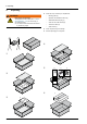
4. Unpacking 4. Unpacking ► WARnInG Risk of injury due to weight The weight of the solar inverter (see “15 Technical Specifications”, p. 80) can cause injury if not handled properly. ► The solar inverter must be lifted and carried by at least two people.
5. Product Description 5. Product Description 5.1 Overview of Components and Connections EN ➀ ➁ ➂ ➃ Fig. 5.1: Solar Inverter Components and Connections no. Component/Connection Description ➀ ➁ ➂ ➃ Status LEDs See Chapter “5.3 Status LEDs”, p. 14 Display and Buttons See Chapter “5.4 Display and Buttons”, p. 14 Type Plate See Chapter “5.2 Type Plate”, p. 12 Electrical Connections See Chapter “5.5 Electrical Connections”, p. 18 Operation and Installation Manual for SOLIVIA 2.0/2.5/3.0/3.
5. Product Description Type Plate VDE 0126-1-1 (D) VDE-AR-N-4105 Country specific standards and settings: see manual IP class: IP65 Safety class: 1 5min. Ambient temp: -25°C...+70°C, derating >55°C SOLIVIA2.0EUG4TR EOE45010459 XX YYWW LLLMMMXXYYWWZZZZZZ www.solar-inverter.com Designed in: Germany Made in: production plant Fig. 5.2: SOLIVIA 2.0 EU G4 TR type plate Country specific standards and settings: see manual IP class: IP65 Safety class: 1 5min. Ambient temp: -25°C...
5. Product Description DC operating volt. range (MPP): DC max. input voltage: DC max. operating current: DC max. current per string: 230V AC nom.output voltage: 50Hz AC nom.output frequency: 16.0A AC max. continuous output current: 3600VA AC max. continuous output power: Cap 0.8~Ind 0.8 AC power factor AC nom.output voltage: AC nom.output frequency: AC max. output current: AC nom. output power: 150-480V 600V 37A 18A 230 220V 50 60Hz 27.2 28.
5. Product Description 5.3 Status LEDs Use ● Exit current menu. ESC Operation Earth Fault Failure Status LEDs no. Label ➀ ➁ ➂ Buttons Symbol ➀ ➁ ➂ Fig. 5.8: 5.4.3 Designation Color OperatiOn Operation Green earth Fault Earth fault Red Failure Failure Yellow Information on the LED messages can be found in “12 Diagnostics and Troubleshooting”, p. 69. 5.4.4 ● ● Cancel value setting. Move upwards in menu. ● ● Set value (increase) Move downwards in menu.
5. Product Description 5.4.5 "Go to Menu" function 5.4.7 Use the nOTE You can use the "Go to Menu" function to directly navigate to a particular menu. A list of the available menu numbers can be found in “16.2 Overview of Menu Structure”, p. 83. 1. To start the Go to Menu function, press the ESC button for at least three seconds. → Press the 3. buttons to set the first digit of the menu number. You can only set menu numbers that actually exist.
5. Product Description 5.4.10 Setting Values You can set various parameters on the display. Use the tons to change the parameter values. The button increases the value of the parameter. The button decreases the value of the parameter. but- The ESC button can be used to cancel the setting, and the original value is then displayed. The button applies the new parameter value. The example on the next page illustrates the procedure for changing the value of a parameter.
5. Product Description Buttons Action Result 12. Select the year using the 13. Press the þ buttons. 110 Date and time ------------------➔Date: 12.01.2013 Time: 14:26:51 button to apply the new value. The value is adopted and the editing mode is exited. Operation and Installation Manual for SOLIVIA 2.0/2.5/3.0/3.3/3.6/5.0 EU G4 TR 110 Date and time ------------------➔Date: 12.01.
5. Product Description 5.5 Electrical Connections 5.5.1 Overview ➀ Fig. 5.11: ➁ 18 ➃ ➄ ➂ ➃ ➄ Electrical Connections for SOLIVIA 2.0, 2.5 EU G4 TR ➀ Fig. 5.12: ➂ ➁ Electrical Connections for SOLIVIA 2.0, 2.5, 3.0, 3.3, 3.6 EU G4 TR Operation and Installation Manual for SOLIVIA 2.0/2.5/3.0/3.3/3.6/5.
5. Product Description ➀ ➁ ➂ ➃ ➄ EN Fig. 5.13: Electrical Connections for SOLIVIA 5.0 EU G4 TR no. Designation ➀ ➁ ➂ ➃ ➄ Description DC connections See Chapter “5.5.2 DC connections and DC isolating switch”, p. 20 DC isolating switch See Chapter “5.5.2 DC connections and DC isolating switch”, p. 20 USB interface See Chapter “5.5.5 USB interface”, p. 20 AC connection See Chapter “5.5.3 AC connection”, p. 20 RS485 interfaces See Chapter “5.5.4 RS485 interface (EIA485)”, p.
5. Product Description 5.5.2 DC connections and DC isolating switch 5.5.4 RS485 interface (EIA485) The solar inverter has two RS485 interfaces to which a PC or a monitoring system can be connected. The RS485 interfaces are internally wired 1:1. This means that both RS485 interfaces can be used as an input or an output. If multiple solar inverters are connected together, each solar inverter must have a unique ID (identification number).
6. Operating Behavior 6. 6.1 Operating Behavior General Principle of Operation The solar inverter converts DC electricity into AC electricity, which is then fed into the local power grid. MPP Tracking The solar inverter has an MPP tracker. The MPP (Maximum Power Point) tracker is an automatic function that searches in regular intervals for the operating point with the highest possible power. On the normal setting, the MPP tracker searches the DC input voltage range near the current operating point.
6. Operating Behavior Warning and Error Messages Every warning or error message is stored in the solar inverter with a time stamp. The messages are stored in the event log or in the internal log, depending on the cause of the error. The event log is primarily intended for the installer and should make analyzing and resolving problems easier. The internal log helps Delta Solar Support when analyzing more difficult problems.
6. Operating Behavior 6.7 Characteristic Curves Efficiency Curves SOLIVIA 2.0 EU G4 TR SOLIVIA 2.5 EU G4 TR Efficiency [%] EN 98 96 94 92 90 not yet available 88 86 84 82 80 1000 500 0 1500 2000 2500 Power [W] 150 V SOLIVIA 3.0 EU G4 TR Efficiency [%] 98 98 96 96 94 94 92 92 90 90 88 88 86 86 84 84 82 82 0 480 V SOLIVIA 3.
7. Installation 7. Installation DAnGER Risk of death by electrocution Potentially fatal voltage is applied to the solar inverter during operation. This potentially fatal voltage is still present for five minutes after all power sources have been disconnected. ► Never open the solar inverter. ► Always disconnect the solar inverter from power before installation, open the DC isolating switch and make sure neither can be accidentally reconnected.
7. Installation 7.1.2 Ambient Conditions 7.1.3 Consideration of Asymmetrical Grid Load ► The solar inverter has an IP65 degree of protection and can be installed indoors or in protected outdoor areas. The use of a SOLIVIA Gateway M1 G2 is mandatory for some installation types. ► Note the operating temperature range at full power without derating and the maximum operating temperature range.
7. Installation – Termination resistor ~ SOLIVIA 5.0 TR L kWh N PE – ~ – ~ SOLIVIA 3.6 TR SOLIVIA 3.6 TR L N PE L kWh N PE – ~ SOLIVIA 11 TR L1 L2 L3 SOLIVIA Gateway M1 G2 N PE kWh L1 L2 L3 N PE Fig. 7.3: 26 Example: Multiple solar inverters connected together Operation and Installation Manual for SOLIVIA 2.0/2.5/3.0/3.3/3.6/5.
7. Installation WARnInG 7.2.2 Installing Mounting Plate You can use the mounting plate as a template for marking the positions of the holes to be drilled. Risk of injury due to weight The solar inverter is very heavy (see “15 Technical Specifications”, p. 80). Incorrect handling can lead to injuries. ► The solar inverter must be lifted and carried by at least two people. A B ∅ Included in delivery: 320 Required Tools and Accessories 200 7.2.1 EN A 6,5 12 Mounting Solar Inverter 12 7.
7. Installation 7.2.3 1. Mounting Solar Inverter 7.3 Attach the solar power inverter to the mounting plate, see Fig. 7.5, p. 28. Grid Connection DAnGER Danger of death or severe injuries from dangerous voltage ► Disconnect the AC conductor from power before removing or inserting the AC plug. 7.3.1 General Instructions The solar power inverter is connected to the local power grid with an AC connection, see Fig. 7.6, p. 28. Fig. 7.
7. Installation recommend using a 20 A residual current device. However, be sure to always adhere to the specific regulations applicable in your country. 7.3.3 1. The typical leakage current is less than 3.5 mA. Establishing Connection Remove the cable sheath as shown and remove 10 mm of insulation from each wire end. nOTE nOTE Observe the correct polarity of the round plug. An incorrect configuration can destroy the solar inverter.
7. Installation ► Insert the wires of the AC cable into the pin insert connections. Observe the correct phase sequence when doing this. ► Tighten the screws of the pin insert to fix the wires in place. 7.4 Connecting the PV Modules DAnGER Danger of death or severe injuries from dangerous voltage Potentially fatal voltage may be applied to the DC connections of the solar inverter. ► Never disconnect the PV modules when the solar inverter is powered.
Not included in delivery: Single-core cable DC+ DC- Grounding kit The grounding kit is required when the DC-PLUS or DC-MINUS side of the solar inverter must be grounded. The grounding kit can be ordered from Delta. A manual is included and can be downloaded under www.solar-inverter.com/eu/de/ grounding-kit.htm. Grounding kit SOLIVIA EU G4 TR grounding kit Delta part number EOE990000275 Connection Socket and Connection Plug DC Connection Type on Solar Inverter The DC-MINUS connection is a socket.
7. Installation 7.4.4 Grounding DC Side 7.5 The solar inverter can be grounded at either the DC+ side or the DC- side. The ground connection must be installed near the solar inverter. We recommend using the grounding kit from Delta. Connecting RS485 (EIA485) - Optional ATTEnTIOn To ensure IP65 protection, all unused connections and interfaces must be closed using the covers on the solar inverter. The DC side of the solar inverter has an insulation and grounding monitor.
7. Installation 7.5.2 Required Tools and Accessories 7.5.3 Connecting Individual Solar Inverters Not included in delivery: – Connection cable from solar inverter to monitoring device ~ Connection cable from solar inverter to solar inverter 8 1 RS485 Cable 3081129500 Termination resistor EN Termination resistor 3072438891 Data logger Fig. 7.
8. Commissioning 8. Commissioning 8.1 Before You Begin The solar inverter must be correctly installed, see “7 Installation”, p. 24. Information on operating the display can be found in “5.4 Display and Buttons”, p. 14. nOTE As long as the commissioning procedure has not been completed, you can go back to any point in the commissioning procedure at any time by pressing the ESC button. nOTE Always read through each step before starting the commissioning procedure. 8.
8. Commissioning 8.3 Commissioning for En 50438 and VDE 0126 Grids The standard commissioning is valid for the following countries and grids. Country Belgium Bulgaria France Greece Italy Grid BE C10/11 12 BG FR UTE Netherlands Portugal Romania Slovakia Spain Czech Republic United Kingdom NL PT RO SK notes EN GR and GR ISLAND IT BT 21 > 6kW ES CZ UK UK UK Italy as per CEI 0-21:2012-06 for PV systems greater than 6 kW.
8. Commissioning Locked power limit ------------------➔Pmax: _._kW Smax: _._kVA 8. To change the value, press the button and then set the value using the buttons. Press the button to apply the value. nOTE: If you change one of the values, you must fill out the provided label after commissioning and place it next to the type plate nOTE: The configured values can only be changed with a PIN after commissioning. nOTE: The configured values are displayed after commissioning in the 131 View Grid Setup menu.
8. Commissioning RS485 ------------------➔ID: 1 Baudrate: 19200 16. To change the value, press the button and then set the value using the buttons. Press the button to apply the value. nOTE: If multiple solar inverters are to be connected via RS485, select a different ID for each inverter. The ID is also used when saving and loading settings in order to identify the solar inverter.
8. Commissioning 8.4 Commissioning for VDE AR n 4105 Grids The commissioning for VDE AR N 4105 grids is valid for the following countries and grids. Country Denmark Germany Grid DK LVD DE LVD notes 1. Check all connections and cables for damage and correct seating. Correct the installation if necessary. 2. Switch on the DC isolating switch. OFF → The startup process of the solar inverter will begin.
8. Commissioning PDD-settings------PDD: Standard ➔continue ------------------- PDD settings ------------------➔Umax: 253V continue 9. Press the press the buttons to select continue and then button. → If the PDD setting is User, an extended PDD Settings menu will be displayed. Continue with Step 10. → If the PDD setting is Standard or Off, the Locked Power Limit menu will be displayed. Continue with Step 12. 10. To change the value, press the button and then set the value using the buttons.
8. Commissioning Date and time ------------------➔Date: 25.05.2012 Time: 14:26:51 ------------------D: ate25 a. n0 d5. t2 i0 m1 e2 Date Time: 14:26:51 ➔continue ------------------RS485 ------------------➔ID: 1 Baudrate: 19200 18. To change the value, press the button and then set the value using the buttons. Press the button to apply the value. 19. Press the press the → buttons to select continue and then button. The RS485 menu is displayed. 20.
8. Commissioning 8.5 Commissioning in Italy for PV Systems Below 6 kW The standard commissioning is valid for the following countries and grids. Country Italy Grid IT BT 21 notes As per CEI 0-21:2012-06 for PV systems equal to or less than 6 kW. 1. Check all connections and cables for damage and correct seating. Correct the installation if necessary. 2. Switch on the DC isolating switch. OFF → EN The startup process of the solar inverter will begin.
8. Commissioning Locked power limit ------------------➔Pmax: _._kW Smax: _._kVA 10. To change the value, press the button and then set the value using the buttons. Press the button to apply the value. nOTE: If you change one of the values, you must fill out the provided label after commissioning and place it next to the type plate nOTE: The configured values can only be changed with a PIN after commissioning. nOTE: The configured values are displayed after commissioning in the 131 View Grid Setup menu.
8. Commissioning RS485 ------------------➔ID: 1 Baudrate: 19200 18. To change the value, press the button and then set the value using the buttons. Press the button to apply the value. nOTE: If multiple solar inverters are to be connected via RS485, select a different ID for each inverter. The ID is also used when saving and loading settings in order to identify the solar inverter.
8. Commissioning 8.6 Commissioning by Loading Settings from Other Solar Inverter It is possible in all countries and for all grids to load the settings from another solar inverter. ATTEnTIOn The IP 65 degree of protection is no longer guaranteed when the USB interface protective cover is removed. ► Only remove the protective cover when necessary. ► Always use the Micro-USB stick provided. The protective cover is designed to fit over the Micro-USB stick. 1.
8. Commissioning 9. Select RS485 ID ➔ ID: 1 Press the the button. → buttons to select the ID and then press The data is then verified and loaded. nOTE: If the message Pendrive error is displayed, make sure the USB drive is properly inserted or that the file is not damaged. A message is displayed when the loading process is successful. Load data Successful Press ENTER 10. Press the → EN button to confirm.
8. Commissioning ENTER: to confirm ESC: to reselect 17. Press the button to complete commissioning. or Press the þ button to change settings. Commissioning is now finished. nOTE 46 ► If the solar inverter is configured to the DE LVD oder DK LVD grids, you can also configure active and reactive power control, see “10.9 Active Power Control”, p. 56. ► The solar inverter offers some optional functions available for all grids, see “10 Settings”, p. 52.
8. Commissioning 8.7 Commissioning After Replacing Solar Inverter It is possible in all countries and for all grids to load the settings from another solar inverter. ATTEnTIOn In this chapter, the term "swap" means the replacement of a damaged solar inverter with a new device of the same type. EN The replacement may only be performed after consulting Delta Solar Support. The support team will discuss the correct procedure with you.
8. Commissioning ---L -o -a -d --U -S -B --d -a -t -a ---Load settings ➔Load swap data ------------------- 8. Press the then press the → buttons to select Load Swap Data and button. The solar inverter will then search for files on the USB drive. nOTE: If the message No files found is displayed, make sure the files are in the main directory of the USB drive. When files are found, the Select RS485 ID menu is displayed. 9. Select RS485 ID ➔ ID: 1 Press the the button.
8. Commissioning ------------------ID: 1 RS485 Baudrate: 19200 ➔continue ------------------ENTER: to confirm ESC: to reselect 16. Press the press the → buttons to select continue and then button. The completion screen will be displayed. 17. Press the EN button to complete commissioning. or Press the button to change settings. þ Commissioning is now finished.
9. Production Information 9. Production Information Structure Submenu 411 Current Overview nOTE All production information is provided for orientation purposes only. The measuring devices and meters provided by the electricity supply company are the authoritative source of information for invoicing. 9.1 Current operating state (see “12 Diagnostics and Troubleshooting”, p.
9. Production Information The 490 History menu shows the statistics for the last seven days the solar inverter was in operation. These seven days do not have to be consecutive. 03 Submenu 491 Day ... ... 490 History ------------------➔Day: 04/15/2012 Day: 04/13/2012 497 Day ... Contents Statistics for energy, runtime, revenue Information on configuring the revenue settings can be found under “10.7 Currency and Credit per kWh”, p. 55.
10. Settings 10. Settings 10.1 Overview Setting Display language Date and time Date and time formats Backlighting and contrast RS485 (EIA485) Currency and Credit per kWh Reset Statistics Active power control Active power reduction Active power by frequency Reactive power control Power factor by active power Constant power factor Local control (Italy only) Shadowing (extended MPP tracker) Insulation and grounding monitoring Standard menu 10.
10. Settings 10.3 Date and time Menu 10.4 110 Date and time Date and time formats Menu 111 Format Description Description Allows the date and time to be configured. Allows the date and time formats to be configured. Accessing the Menu Accessing the Menu Main menu > Install settings > Date and Time Main Menu > Install Settings > Date and Time > Format 1.
10. Settings 10.5 Backlighting, contrast Menu 10.6 120 Display settings RS485 (EIA485) Settings Menu 140 RS485 Description Description Allows backlighting and contrast to be configured. Allows the ID and baudrate of the RS485 interface to be configured. Accessing the Menu Accessing the Menu Main Menu > Install Settings > Display Settings Main Menu > Install Settings > RS485 1.
10. Settings 10.7 Currency and Credit per kWh Menu 470 Feed-In Settings 10.8 Reset Statistics Menu 471 Statistics Description Description Allows the currency and credit per kWh to be configured. The statistics can also be reset. Allows the statistics to be reset. The currency and credit per kWh can also be configured.
10. Settings 10.9 Active Power Control nOTE 10.9.2 Active Power Reduction Menu Active power control is only available for DE LVD and DK LVD grids. 511 Power Reduction nOTE The settings in the 511 Power Reduction menu affect the "Power Factor by Active Power cos φ (P)" function, see “10.10.2 Power Factor by Active Power cos φ (P)”, p. 58. nOTE Changes to active and reactive power control can affect energy production. Ask your installer before changing the settings. 10.9.
10. Settings 10.9.3 Active Power by Frequency P(f) Accessing the Menu Main Menu > User Settings > Active PwCtrl > Power vs freq Menu 512 Power/Frequency Description Allows the statistics to be reset. The currency and credit per kWh can also be configured. This function alters the fed active power depending on the grid frequency. If a starting frequency is exceeded, the fed active power is limited. If a stopping frequency is exceeded, the active power is no longer fed.
10. Settings 10.10 Reactive Power Control 10.10.2 Power Factor by Active Power cos φ (P) nOTE Menu Reactive power control is only available for DE LVD and DK LVD grids. 520 Reactive PwCtrl Description This function can be used to determine a separate cos φ for four different power ratios P/Pn (see “Fig. 10.3 Setting Ranges for “cos φ (P)” Function”, p. 58). nOTE Changes to active and reactive power control can affect energy production. Ask your installer before changing the settings. 10.10.
10. Settings Example Accessing the Menu The parameters for points A to D are configured in this example as follows: Main Menu > User Settings > Reactive PwCtrl Display Text A cos phi: ind 1.00 Description Point A: cos φ is set to inductive 1.00. Since cos φ = 1.00, capacitive could also be configured. The power ratio P/Pn is automatically set to 0% and cannot be changed. Point B: cos φ is set to inductive 1.00. Point B: Power ratio P/Pn is set to 23 %. Point C: cos φ is set to capacitive 1.00.
10. Settings 10.11 Local Control (Italy only) 10.10.3 Constant Power Factor cos φ Menu 520 Reactive PwCtrl nOTE This function is only available for the IT BT 21 grid. Description Allows a constant cos φ power factor to be configured. Accessing the Menu Menu 500 User Settings Main Menu > User Settings > Reactive PwCtrl Options USB S fO eL aI tV uI rA es## Production info ➔User settings Diagnostic&Alarm 1. In the main menu, press the buttons to select User Settings and then press the button.
10. Settings 10.12 Shading (extended MPP tracker) 10.13 Insulation and grounding monitoring Menu Menu 210 Shadowing 220 Grounding Description Description The "Shading" option is an extended MPP tracker. When the option is switched on, the MPP tracker performs an additional search at regular intervals. The DC side of the solar inverter has an insulation and grounding monitor. The MPP tracker then searches for the maximum power over a wider voltage range.
10. Settings 10.15 Changing Grid 10.14 Standard menu Menu ATTEnTIOn 800 Standard Menu If the selected grid is changed, a completely new commissioning process is started, see “8 Commissioning”, p. 34. Description A standard menu can be defined, which is automatically displayed when the display buttons are not used for a certain period of time. When the standard menu is displayed, pressing the ESC button displays the main menu. The standard menu is set at the factory to 411 Current Overview.
11. Saving and Loading Data and Settings 11. Saving and Loading Data and Settings ATTEnTIOn The IP 65 degree of protection is no longer guaranteed when the USB interface protective cover is removed. ► Only remove the protective cover when necessary. ► Always use the Micro-USB stick provided. The protective cover is designed to fit over the Micro-USB stick. 11.1 Before You Begin Information on operating the display can be found in “5.4 Display and Buttons”, p. 14. same, the file name is also the same.
11. Saving and Loading Data and Settings 11.3 Firmware Updating The firmware can be updated via the USB interface. The firmware update is performed in the solar inverter in two steps: ● Manual loading of data from USB drive ● Automatic updating of solar inverter's individual controllers It is possible to load the data under AC or DC voltage. The data can also be loaded at night with no DC voltage. The solar inverter's individual controllers can, however, only be updated under DC voltage.
11. Saving and Loading Data and Settings 11.4 Saving Settings The solar inverter settings can be saved to be loaded to another solar inverter of the same type for use with the same settings. The saved settings are: ● Grid settings ● User settings ● Display settings ● Production settings ------------------InstS aO lL lIV sI eA tt# i# ngs Options ➔USB features Production info Without cover, you will lose the IP65 protection.
11. Saving and Loading Data and Settings 11.5 Loading Settings To simplify the setup procedure, the settings from another solar inverter of the same type can be loaded and used in another solar inverter for use with the same settings. Information on saving the settings can be found in “11.4 Saving Settings”, p. 65. ------------------InstS aO lL lIV sI eA tt# i# ngs Options ➔USB features Production info 1. → 2. Without cover, you will lose the IP65 protection.
11. Saving and Loading Data and Settings 11.6 Saving Swap Data nOTE In this chapter, the term "swap" means the replacement of a solar inverter with a new device of the same type, without changing the installation parameters, e.g., those of the PV modules. EN The replacement may only be performed after consulting Delta Solar Support. The support team will discuss the correct procedure with you.
11. Saving and Loading Data and Settings 11.7 Creating Reports The reports contain the following information: ● Firmware/serial number of the model ● Statistics, events, comparisons with a summary of statistics and events ● Internal logs ● AT reports ● LVD reports (only for DE LVD and DK LVD grids) ------------------InstS aO lL lIV sI eA tt# i# ngs Options ➔USB features Production info Without cover, you will lose the IP65 protection.
12. Diagnostics and Troubleshooting 12. Diagnostics and Troubleshooting 12.1 Messages on Current Operating Status The following message categories are defined for displaying the operating status of the solar inverter: Message Category Limited operation External event ● Insulation and grounding failure Internal event Change events Description Non-critical factors that can affect the production results but which are not failures (e.g., self-test).
12. Diagnostics and Troubleshooting Messages on the current operating status are shown by the LEDs and text messages on the display in the 411 Current Overview menu. When an event occurs, the 411 Current Overview menu automatically displays. A brief description of the event is then shown on the fourth display line. 411 Current overview Now: ____W Day: ____Wh External events The software of the solar inverter determines whether a warning is given or a failure occurs.
12. Diagnostics and Troubleshooting 12.2 Analyzing Failures When a warning is given or a failure shown by the LEDs and the 411 Current Overview menu, additional information can be displayed. This is generally divided into two categories: ● External events (incl. insulation and grounding failures) ● Internal events EN The additional information on the failures are logged in two separate menus: ● External events: Menu 480 Ext.
12. Diagnostics and Troubleshooting 12.2.2 Procedure for Internal Events 1. 620 Internal log 2. You can view the whole list by pressing the buttons. If multiple failures occur, multiple failure numbers are displayed. 3. Contact Delta Solar Support and provide the displayed failure numbers. nOTE: For internal events, always contact Delta Solar Support before attempting to resolve the failure. → 16.04.2012 17:25:36 202 222 72 Press the button in the 411 Current Overview menu.
12. Diagnostics and Troubleshooting 12.3 LEDs Overview of Failure Messages/Troubleshooting Display message Message description Warning ### Fault correction Internal failure ("Warning" + three-digit number) ► Failure ### Internal failure ("Failure" + three-digit number) ► L1 Voltage failure Check the grid frequency shown on the display (412 Current Data AC menu). ► If no voltage is present, check the automatic circuit breaker. DC feed-in failure.
12. Diagnostics and Troubleshooting LEDs Display message Message description PV1 ISO running fail Fault correction Operating insulation <150 kΩ. ► PV1+ Grounding fail PV1- Grounding fail PV1 Voltage too low DC+/DC- not correctly grounded. ► Check the GND connection. The DC voltage is too low. ► L1 power reduction PV1 PW limit to Pn PV1 temp derating Check the insulation resistance at the DC side of the PV modules. Check the PV cell voltage shown on the display (416 Current Data PV menu).
12. Diagnostics and Troubleshooting 12.4 Message Logs 12.4.2 "Internal Events" Log All important events and messages are logged in the solar inverter. Menu The following logs are created: ● External events ● Internal events ● Log for VDE AR N 4105 ● Change events ● Autotest for Italy 620 Internal log Accessing the Menu Main menu > Diagnostic&Alarm > Internal Log Options USB S fO eL aI tV uI rA es## Production info ➔Diagnostic&Alarm Inverter info 1.
12. Diagnostics and Troubleshooting 12.4.3 Log for VDE AR n 4105 Menu 640 Report LVD 12.4.4 "Change Events" Log Menu 482 Change events Description Description For grids in accordance with VDE AR N4105, the last five failure messages must be saved in a separate log. The log contains a chronological list of all changes that affect energy production and thereby profit. The log is only available fo the grids DE LVD and DK LVD.
12. Diagnostics and Troubleshooting 12.5 Current Grid Settings Menu 12.6 131 View Grid Setup Description Menu 610 IT Autotest EN Description The current grid settings can be displayed using 131 View Grid Setup The contents of this menu are write-protected. Accessing the Menu Main Menu > Install Settings > Grid Selection > View Grid Setup 1. In the main menu, press the SOLIVIA ## buttons to select Install ------------------Settings and then press the ➔Install settings button.
12. Diagnostics and Troubleshooting Displaying Autotest Reports The reports from the last five autotests can be shown on the display. Additionally, the autotest reports can be saved to a USB drive, see “11.7 Creating Reports”, p. 68. Main Menu > Diagnostic&Alarm > IT Autotest > Perform Autotest Options 1. In the main menu, press USB S fO eL aI tV uI rA es## buttons to select the Production info Diagnostic&Alarm and then ➔Diagnostic&Alarm press the button.
13. Maintenance and Repair 13. Maintenance and Repair DAnGER Risk of death by electrocution Potentially fatal voltage is applied to the solar inverter during operation. This potentially fatal voltage is still present for five minutes after all power sources have been disconnected. ► Never open the solar inverter. The solar inverter contains no components that must be maintained or repaired by the operator or installer. Opening the cover will void the warranty. 14. 14.
15. Technical Specifications 15. Technical Specifications Input (DC) SOLIVIA 2.0 SOLIVIA 2.5 SOLIVIA 3.0 SOLIVIA 3.3 SOLIVIA 3.6 SOLIVIA 5.0 Maximum recommended PV power 2400 WP 3030 WP 3700 WP 4000 WP 4300 WP 6000 WP Rated power 2200 W 2750 W 3300 W 3600 W 3850 W 5500 WP Maximum input voltage 125 - 600 V MPP working range 150 - 480 V 170 - 480 V 150 - 480 V Rated current 6.2 A @ 360 V 7.2 A @ 360 V 9.2 A @ 360 V 10.0 A @ 360 V 10.7 A @ 360 V 15.
15. Technical Specifications General Specifications Model name Delta part number Max. efficiency EU efficiency Max. operating temperature range Operating temperature at full power without throttling Storage temperature range Humidity Max. operating height SOLIVIA 2.0 SOLIVIA 2.0 EU G4 TR EOE45010459 95.8% 93.1% General Specifications Model name Delta part number Max. efficiency EU efficiency Max.
16. Appendix 16. Appendix 16.1 Order numbers Grounding kit The ground connection must be installed near the solar inverter. We recommend using the "Grounding Kit MC4" grounding kit from Delta. Grounding kit Grounding Kit MC4 Delta part number EOE990000275 Cable couplings Cable coupling types for the DC connections to the inverter. The DC+ connection of the solar inverter is a plug, the DC– connection is a socket.
16. Appendix 16.2 Overview of Menu Structure nOTE You can use the "Go to Menu" function to directly navigate to a particular menu. 1. EN To open the Go to Menu function, press the ESC button for at least three seconds. → Go to Menu opens. Go to menu ➔Menu: 411 411 Current data 2. Press the → 3. button to enter the menu number. The first digit flashes. buttons to enter the first digit of the menu numUse the ber and then press the button. → The second digit flashes. 4.
16. Appendix Main Menu 100 Install Settings 100 Install Settings 200 Options Language: 300 USB features Date and time 110 Date and time 400 Production Info Display settings Date 500 User Settings Grid selection Time 600 Diagnostic&Alarm RS485 Format German 111 Format Date 700 Inverter Info 800 Standard menu 120 Display settings Time Backlight Contrast 130 Grid Selection View grid setup Grid Change Custom.
16. Appendix 400 Production Info 410 Current Data 410 Current Data 420 Day Statistics Current Overview 411 Current Overview 430 Week Statistics Current Data AC Now 440 Month Statistics Current Data PV Day 450 Year Statistics Date and time Curr. operating state 460 Total Statistics Current Insulation 470 Feed-In Settings 412 Current Data AC 480 Event Journal L1 voltage 490 History L1 current EN L1 freq. L1 P L1 Q L1 DC inj.
SUPPORT - EUROPE Austria Italy service.oesterreich@solar-inverter.com 0800 291 512 (Free Call) supporto.italia@solar-inverter.com 800 787 920 (Free Call) Belgium The netherlands support.belgium@solar-inverter.com 0800 711 35 (Free Call) ondersteuning.nederland@solar-inverter.com 0800 022 1104 (Free Call) Bulgaria Portugal support.bulgaria@solar-inverter.com +421 42 4661 333 suporte.portugal@solar-inverter.com +49 7641 455 549 Czech Republic Slovakia podpora.czechia@solar-inverter.