
User Manual

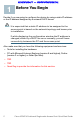


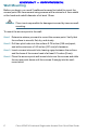

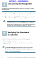

Table Of Contents
- AP541N Dual-band Single-radio Access Point Quick Start Guide
- Package Contents
- Welcome
- Before You Begin
- Getting to Know the Cisco AP541N
- Installing the Cisco AP541N
- Step 1 Attach the antennas to the RP-TNC connectors labeled ANT101, ANT102, and ANT103. The antennas are all the same, so which antenna is attached to what connector is of no consequence.
- Wall Mounting
- Before you begin, you need 2 wallboard screws (included) to mount the access point. We recommend using screws with a minimum of 4mm width at the head and a shaft diameter of at least 1.5mm.
- Step 1 Determine where you want to mount the access point. Verify that the surface is smooth, flat, dry, and sturdy.
- Step 2 Drill two pilot holes into the surface 5.75 inches (146 mm) apart, and with a minimum of 4.0 inches (101 mm) of clearance.
- Step 3 Insert a screw into each hole, leaving a gap between the surface and the base of the screw head of at least 0.1 inches (3 mm).
- Step 4 Place the access point wall-mount slots over the screws and slide the access point down until the screws fit snugly into the wall- mount slots.
- Flat Surface Installation
- Connecting the Equipment
- Verifying the Hardware Installation
- Getting Started with the Configuration
- Display the Configuration GUI and Enable the Radio
- Step 1 Power on the PC and configure the PC IP address to an IP address in the same subnetwork. The default Cisco AP541N IP address is 192.168.10.10. For example, you can set the:
- Step 2 Connect an Ethernet cable to an Ethernet port on the PC.
- Step 3 Connect the other end of the PC Ethernet cable to an Ethernet port on a switch, hub, or the Cisco AP541N Ethernet port. If you connected the PC through a switch or a hub, connect the Cisco AP541N to that device by using another Ethernet cable.
- Step 4 Power on the access point.
- Step 5 Open a Web browser window. If you are prompted to install an Active-X plug-in when connecting to the device, follow the prompts to accept the plug-in.
- Step 6 Enter the Cisco AP541N IP address in the address bar and press Enter. For example, enter http://192.168.10.10. The login window displays.
- Step 7 Enter the default username cisco and the default password cisco. (Passwords are case sensitive.) The configuration window displays.
- Step 1 Power on the PC and configure the PC IP address to an IP address in the same subnetwork. The default Cisco AP541N IP address is 192.168.10.10. For example, you can set the:
- Troubleshoot Your Connection
- Display the Configuration GUI and Enable the Radio
- Returning the Cisco AP541N to the Factory Default Settings
- Where to Go From Here

6 Cisco AP541N Dual-band Single-radio Access Point Quick Start Guide
REVIEW DRAFT — CISCO CONFIDENTIAL
Wall Mounting
Before you begin, you need 2 wallboard screws (included) to mount the
access point. We recommend using screws with a minimum of 4mm width
at the head and a shaft diameter of at least 1.5mm.
WARNING Cisco is not responsible for damages incurred by insecure wall-
mounting.
To mount the access point to the wall:
STEP 1 Determine where you want to mount the access point. Verify that
the surface is smooth, flat, dry, and sturdy.
STEP 2 Drill two pilot holes into the surface 5.75 inches (146 mm) apart,
and with a minimum of 4.0 inches (101 mm) of clearance.
STEP 3 Insert a screw into each hole, leaving a gap between the surface
and the base of the screw head of at least 0.1 inches (3 mm).
STEP 4 Place the access point wall-mount slots over the screws and slide
the access point down until the screws fit snugly into the wall-
mount slots.