English Operating manual Thermocouple Data Logger HD32.8.8 – HD32.8.16 Companies / Brands of GHM www.deltaohm.com Keep for future reference.
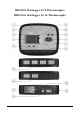
HD32.8.8 Datalogger for 8 Thermocouples HD32.8.16 Datalogger for 16 Thermocouples HD32.8 - 2 - V1.
HD32.8.8 and HD32.8.16 1. ON/OFF key: It turns the instrument on and off. 2. TIME key: It allows the display of date and time, in the first line for about 8 seconds. 3. SHIFT FNC key: It activates the Shortcut window. 4. Graphic display. 5. Function keys F1, F2, F3: Activate the function in the bottom line of the display. 6. ENTER key: In the menu, it confirms the data entered. 7. ESC key: It allows to exit from the menu or, in case of a submenu, to exit from the current level display. 8.
TABLE OF CONTENTS 1. GENERAL CHARACTERISTICS ....................................................................................................................... 6 2. KEYBOARD AND DISPLAY DESCRIPTION ................................................................................................... 7 2.1 The Display ..................................................................................................................................................... 8 2.2 The Keyboard ......................
11.1 Connection to the RS232C serial port ............................................................................................................39 11.2 Connection to the USB 2.0 port .....................................................................................................................39 12. FUNCTIONING NOTES AND OPERATING SAFETY ..................................................................................40 13. TECHNICAL CHARACTERISTICS..............................................
1. GENERAL CHARACTERISTICS The HD32.8.8 and HD32.8.16 are two dataloggers for thermocouples that can capture, log and then send to a PC or serial printer the data coming from the 8 or 16 thermocouples. The instruments can work with thermocouple of type K, J, T, N, R, S, B or E. During the measuring phase, the connected probes must be of the same type.
2. KEYBOARD AND DISPLAY DESCRIPTION The user interface consist of a backlit LCD display and the power-on, function, and setting keys. Turn the instrument on and off with the ON/OFF key. When you turn the instrument on, the logo and model will be displayed for a few seconds, and then the main display. In this phase, the instrument detects the inputs where the probes are connected and the unused inputs.
2.1 THE DISPLAY The HD32.8 standard display is divided in two areas: The first area displays, from top to bottom, the battery’s charge status and the current time, the type of selected thermocouple, and the temperatures measured by the probes connected to the inputs. The bottom line displays the options that can be activated using the F1, F2 and F3 keys. Please see the SHIFT FNC key in the following paragraph.
SHIFT FUNCTION key It activates the Shortcut window. A drop-down menu opens as in the figure: The black background item is the active item. To select another item, use the ▲▼ arrows and confirm with ENTER. F1, F2, F3 keys These are “function keys”: They activate the function in the lower line of the display (indicated by the arrow in the figure); the function, enabled by SHIFT FNC, is selected and displayed in “reverse” (e.g. in the figure the “°C” function is enabled).
MEM key It allows to start and end a “logging” session (data recording); the data logging interval must be set in the menu. PRINT key It allows direct printing of the data via the serial port; the data printing interval must be set in the menu. Arrow keys Allow navigation through the menus, selection of the type of thermocouple, and choice of the inputs to be displayed. During measurement, you can select the type of thermocouple using the ▲▼ arrows.
3. OPERATION Connect the probes to the inputs located in the lower part of the instrument, and turn the HD32.8 datalogger on with the key. Using the ▲▼ arrows, select the type of thermocouple used (Tc type). On the display you will see the values measured by the first four connected probes. To view the other probes, use the ◄► arrows. If a probe is disconnected when the instrument is on, the value on the display is replaced by a series of dashes: Reconnect the probe to view the new data.
3.2 THE MAXIMUM, MINIMUM AND AVERAGE VALUES OF THE CAPTURED QUANTITIES In order to display the maximum, minimum and average values of the measured quantities, proceed as follows: 1. Use SHIFT FNC to open the drop-down menu; 2. Use the arrows ▲▼ to select “data”; 3. Confirm by pressing ENTER: The selected quantity is displayed in the central line of the display; 4. The three items max (maximum), min (minimum) and avg (average) are shown in the bottom line of the display using F1 or F2.
During logging, the LOG indication is displayed, the battery symbol blinks and a beep is issued each time a logging occurs. To end the logging, press MEM again. The instrument can turn off during logging between one capture and the next: The function is controlled by the Self_shut_off_Mode menu parameter.
4. MAIN MENU To access the programming menu press SETUP. The setting menu will be displayed with the following items: 0) 1) 2) 3) 4) 5) 6) 7) 8) 9) Info Logging Serial Reset Contr. Firmware Time/date Calibrate Key lock Password If you do not press any key within 2 minutes, the instrument goes back to the main display. Use the arrows ▲▼ ◄► and press ENTER to select an item. To exit the selected item and return to the previous menu, press ESC.
4.2 LOGGING MENU To access the Logging menu, open the main menu using the SETUP key. Using the ▲▼ ◄► arrows, select Logging and confirm with ENTER. The parameter setting submenu for the logging sessions will be displayed. You can set the data capture frequency (Log interval) and the automatic log g ing start (Start/ s to p tim e). T h e cap t ur e in t er v al is t h e sam e f o r al l p r o b es. With the “Log File Manager” you can handle the stored data sessions: printing, erasure. 4.2.
Once you have accessed the LOGGING submenu (previous par.) use the arrows ▲ ▼ to select Self shut-off mode: • If the set Log Interval (see previous par.) is lower than 60 seconds, the following will be displayed • If the set Log Interval (see previous par.) is greater or equal to 60 seconds, the following screen will be displayed 1. By using the arrows ▲ ▼ you can select: STAY ON (the instrument stays on) SHUT OFF (the instrument shuts off between one logging and the next) 2.
1. Press ENTER to confirm the data prompted by the instrument; 2. To change the prompted data, use the arrows ◄ ► to select the data to be changed (year/month/day and hour:minutes:seconds); 3. The selected data will flash; 4. Use the arrows ▼▲ to change its value; 5. Confirm by pressing ENTER; 6. Press ESC to return to the Logging menu without making any change; 7. Press ESC again to return to the main menu; 8. Press SETUP to exit immediately from the menu.
10. Press ENTER to confirm or ESC to exit without enabling the automatic start: In both cases, you will return to the LOGGING menu. 11. Press SETUP to exit immediately from the main menu. When the instrument starts automatically a LOG session, a beep is issued on each capture and the blinking LOG message is shown at the top of the display. Press MEM to stop the session before the set time. To cancel the automatic start setting, use the Cancel auto start function as illustrated in the following paragraph.
4.2.4 Cancel auto start Once the LOG session start and end times are set, you can inhibit the session automatic start by using Cancel auto start. Once you have accessed the LOGGING submenu: 1. Use the arrows ▲ ▼ to select Cancel auto start; 2. The LOG session start and end times will be displayed: 3. By pressing ▲ the following message will be displayed: “Self timer not active”; 4. 5. 6. 7.
Once you have accessed the LOGGING submenu: 1. Use the arrows ▲ ▼ to select Log File manager: You will see the following submenu 0) Print selected log 1) Erase ALL logs 2) Select memory type 2. 3. 4. 5. Use the arrows ▲▼ to select a menu item; Press ENTER to confirm; Press ESC to return to the menu; Press SETUP to exit immediately from the main menu. NOTE: You can connect a PC or serial port printer to the instrument RS232C serial port.
0) Print selected log: By selecting this item, the page of the log to be printed will be displayed: 1. Use the arrows ▲▼◄►to select the log to be printed, and the F1 and F3 function keys to shift page. 2. Once a file is selected, the acquisition start date and time and the number of samples contained in the file (Rec) are displayed at the bottom of the display. Warning: The files are stored in ascending order.
The memory can be handled in two modes that can be selected using the ▲▼ arrows: • Circular memory. When the memory is full, the new files will overwrite the oldest ones. • Until memory full. When the memory space is full, the recording will stop and the message “WARNING: MEMORY FULL!!” will be displayed. In order to continue recording, the files in the memory should be erased. 1. Press ENTER to confirm the selected mode; 2. Press ESC to cancel the operation and return to the previous menu level; 3.
4.3.1 The Baud Rate The Baud Rate indicates the speed used for the serial communication with the PC. To set the Baud rate, proceed as follows: 1. Use the arrows ▲▼ to select the item; 2. Press ENTER: You will get the following message: 3. Use the arrows ▼▲ to set the value; 4. Press ENTER to confirm and return to the previous page, or press ESC to cancel the change and exit the menu item; 5. Press ESC over and over to exit from the submenus; 6. Press SETUP to exit immediately from the main menu.
data printing is started when the PRINT key is pressed. Press PRINT again to end the continuous printing. Select a sufficiently long print interval so that the printer connected to the instrument can actually perform the printing. 4.4 RESET To restore the factory settings, reset command was designed for a complete reset of the instrument. To access the Reset submenu, proceed as follows: 1. Press SETUP; 2. Use the arrows ▲▼ to select Reset; 3. Press ENTER: You will get the following message 4.
4.6 FIRMWARE This menu item allows displaying the information concerning the date and firmware version. To access the Firmware submenu, proceed as follows: 1. Press SETUP; 2. Use the arrows ▲▼◄► to select Firmware; 3. Press ENTER; 4. This page will open 5. Press ESC to return to the main menu; 6. Press SETUP to exit immediately from the main menu. 4.7 TIME/DATE This menu item allows setting the date and time that will be shown at the top of the display.
4.8 CALIBRATE The Calibrate menu is reserved to Technical Support. It reports the last calibration date. To access the Calibrate submenu, proceed as follows: 1. Press SETUP; 2. Use the arrows ▲▼◄► to select Calibrate; 3. Press ENTER; 4. You will get the following message 5. Press ENTER or ESC to return to the main menu: You cannot perform any change, calibration is reserved to Technical Support; 6. Press SETUP to exit immediately from the main menu.
WARNING! When the instrument is locked by a password, all keys are locked, except MEM, used to start the LOG session (data capture) and SETUP, ENTER and ESC that allow entering the main menu to unlock the instrument. Therefore the user has to first set all required parameters, protect the instrument using the KEY LOCK function and start the LOG session, in order to prevent any undesired access by unauthorized personnel.
9. You will get the message “Insert new password”; 10. Use the arrows ▼▲ to enter the new password; 11. Press ENTER to confirm (or ESC to cancel) and return to the main menu; 12. Press SETUP to exit immediately from the main menu. WARNING! Using the User password you can lock/unlock the instrument (see Paragraph “4.9 KEY LOCK”). HD32.8 - 28 - V1.
5. PROBES AND MEASUREMENTS You can connect the thermocouple temperature probes of type K, J, T, N, R, S, B and E to the HD32.8.8 and HD32.8.16 dataloggers. The selection is done using the ▲▼ arrows (see chapter 3. OPERATION). The contacts of the thermocouple probe connector are polarized. They must be inserted on the standard miniature socket located on the instrument in the correct direction. These probe positive pole is usually marked with a "+" sign, as shown in the following drawing.
The temperature measured by immersion is carried out by inserting the probe in the liquid where you wish to perform the measurement; the hot junction is housed in the end part of the probe. In the temperature measured by penetration the probe tip must be inserted into the material; the hot junction is housed in the end part of the probe. NOTE: When measuring the temperature on frozen blocks it is convenient to use a mechanical tool to bore a cavity in which to insert the tip probe.
6. INSTRUMENT SIGNALS AND FAULTS The following table lists the instrument indications, the errors and the information supplied to the user. Display indication Explanation ----- This appears if the probe, already detected during turn on, is disconnected or faulty. Over Overflow appears when the probe detects a higher value than expected measurement range for that type of thermocouple.
7. BATTERY SYMBOL AND BATTERY REPLACEMENT, MAINS POWER SUPPLY The battery symbol on the display constantly shows the battery charge status. To the extent that batteries have discharged, the symbol “empties”. When the charge decreases still further it starts blinking. In this case, batteries should be replaced as soon as possible. If you continue to use it, the instrument can no longer ensure correct measurement. Data stored on memory are maintained even without power supply.
The external power supply connector has an external diameter of 5.5mm and an internal diameter of 2.1mm. Warning: The power supply cannot be used as a battery charger. If the instrument is connected to the external power supply, the [~] symbol is displayed instead of the battery symbol. Malfunctioning upon turning on, after battery replacement After replacing the batteries, the instrument may not restart correctly; in this case, repeat the operation.
9. SERIAL INTERFACE AND USB The HD32.8 is fitted with an electrically isolated RS-232C serial interface, and an USB 2.0 interface. Optionally, we can supply a serial cable with sub D 9-pole female connectors (code 9CPRS232) or a cable with USB 2.0 connectors (code CP22). The USB connection requires the previous installation of a driver contained in the DeltaLog9 CDROM. Install the driver before connecting the USB cable to the PC (please see the documentation provided with DeltaLog9 CD-ROM).
Command LDnn Response LEX LFnn & Start on; 2007/01/01 00:37:32; rec;000003 LN 00 ; 01 ; 02 ; 03 ; . ; . ; . ; P0 P1 RA RL S0 S1 WA# & & Sample log = 30sec Sample print = 0sec WC0 WC1 WL# & & & HD32.8 & Description Print data stored in section nn. (nn= hexadecimal number 0063). If the section is empty: “-->No Log Data<--” Cancel data stored in all sections. Print memory nn section status. The number, and storage start date and time are displayed. (nn= hexadecimal number 00-63).
10. STORING AND TRANSFERRING DATA TO A PC The HD32.8 instrument can be connected to a personal computer via an RS232C serial port or USB port, and exchange data and information through the Deltalog9 software (vers. 3.0 and later) running in a Windows operating environment. It is possible to print the measured values on an 80 column printer (PRINT key) or store them in the internal memory using the Logging function (MEM key). If necessary, the data stored in the memory can be transferred later to a PC. 10.
Number of connected probes Number of samples that can be stored 13 14 15 16 56000 56000 48000 48000 The time required to fill the memory depends on the number of connected probes and the selected logging interval. The following tables report this time, in the format days:hours:minutes:seconds.
10.1.2 The Erase function: clearing the memory To clear the memory use the Erase Log function (see par. “4.2.5 Log File Manager”). The instrument starts clearing the internal memory; at the end of the operation, it goes back to normal display. NOTES: • Data transfer does not cause the memory to be erased: The operation can be repeated as many times as required. • The stored data remain in the memory independently of the battery charge conditions.
11. CONNECTION TO A PC The HD32.8 is fitted with two ports for connecting the instrument to the PC: - RS232C serial port with null modem cable code 9CPRS232. The cable has two sub D 9-pole female connectors. - USB 2.0 port with the cable code CP22. The cable has a USB type A connector for PC connection and a USB type B connector for connection to the instrument. The instrument is supplied with the DeltaLog9 software (vers. 3.0 and later).
12. FUNCTIONING NOTES AND OPERATING SAFETY Authorized use Comply with the technical specifications outlined in the next chapter. Its use is authorized only in conformity with the instructions written in this manual. Any different use is considered improper. General instructions on security This instrument has been manufactured and tested according to safety regulation EN 61010-1:2010 concerning electronic measurement instruments and was delivered ex factory in perfect security conditions.
13. TECHNICAL CHARACTERISTICS Instrument Dimensions (Length x Width x Height) Weight Materials Display 220x180x50 mm 1100 g (batteries included) ABS, polycarbonate and aluminium Backlit LCD, Dot Matrix 128x64 points, visible area 56x38mm Operating conditions Operating temperature Warehouse temperature Working relative humidity Protection degree -5 … 50°C -25 … 65°C 0 … 90% RH without condensation IP64 Power Batteries Mains adapter (code SWD10) 4 1.
Instrument accuracy and measurement range Tc: K -200…+1370°C / ±0.1°C up to 600°C ±0.2°C over 600°C Tc: J -100…+750°C / ±0.1°C up to 400°C ±0.2°C over 400°C Tc: T -200…+400°C / ±0.1°C Tc: N -200…+1300°C / ±0.1°C up to 600°C ±0.2°C over 600°C Tc: R +200…+1480°C / ±0.3°C Tc: S +200…+1480°C / ±0.3°C Tc: B +200…+1800°C / ±0.4°C Tc: E -200…+750°C / ±0.1°C up to 300°C ±0.2°C over 300°C The precision only refers to the instrument.
Tolerance of the thermocouple probes: The tolerance of a type of thermocouple corresponds to the maximum acceptable deviation from the e.m.f. of any thermocouple of that type, with reference junction at 0°C. The tolerance is expressed in degrees Celsius, preceded by the sign. The tolerances refer to the operating temperature expected for the thermocouple, in agreement with the diameter of the thermoelements. TOLERANCE CLASSES OF THERMOCOUPLES Tolerances according to IEC 60584-2 standard.
14. ORDERING CODES HD32.8.8 HD32.8.16 DeltaLog9 8-input data logger instrument for temperature probes with thermocouples type K, J, T, N, R, S, B, and E. The kit is composed of the HD32.8.8, 4 1.5V alkaline C-BABY type batteries, operating manual, DeltaLog9 software (vers. 3.0 and later), and bearing and transport belt. The probes, tripod support, suitcase and cables must be ordered separately. 16-input data logger instrument for temperature probes with thermocouples type K, J, T, N, R, S, B, and E.
NOTES HD32.8 - 45 - V1.
NOTES HD32.8 - 46 - V1.
GU AR AN T E E TERMS OF GUARANTEE All DELTA OHM instruments are subject to accurate testing, and are guaranteed for 24 months from the date of purchase. DELTA OHM will repair or replace free of charge the parts that, within the warranty period, shall be deemed non efficient according to its own judgement. Complete replacement is excluded and no damage claims are accepted. The DELTA OHM guarantee only covers instrument repair.
GHM GROUP – Delta OHM | Delta Ohm S.r.l. a socio unico Via Marconi 5 | 35030 Caselle di Selvazzano | Padova | ITALY Phone +39 049 8977150 | Fax +39 049 635596 www.deltaohm.com | info@deltaohm.com The quality level of our instruments is the result of the constant development of the product. This may produce some differences between the information written in this manual and the instrument you have purchased. We cannot completely exclude the possibility of errors in the manual, for which we apologize.
GHM GROUP – Delta OHM | Delta Ohm S.r.l. a socio unico Via Marconi 5 | 35030 Caselle di Selvazzano | Padova | ITALY Phone +39 049 8977150 | Fax +39 049 635596 www.deltaohm.com | info@deltaohm.com V1.